
Gateway Load Balancing Protocol GLBP Tutorial
The main disadvantage of HSRP and VRRP is that only one gateway is elected to be the active gateway and used to forward traffic whilst the rest are unused until the active one fails. Gateway Load Balancing Protocol (GLBP) is a Cisco proprietary protocol and performs the similar function to HSRP and VRRP but it supports load balancing among members in a GLBP group. In this tutorial, we will learn how GLBP works.
| Note: Although we can partially configure load balancing via HSRP or VRRP using multiple groups but we have to assign different default gateways on the hosts. If one group fails, we must reconfigure the default gateways on the hosts, which results in extra administrative burden. |
Note: Although GLBP is no longer a topic in current ENCOR syllabus but you may see some questions related to it so it is better to learn GLBP as well.
GLBP Election
When the routers are configured to a GLBP group, they first elect one gateway to be the Active Virtual Gateway (AVG) for that group. The election is based on the priority of each gateway (highest priority wins). If all of them have the same priority then the gateway with the highest real IP address becomes the AVG. The AVG, in turn, assigns a virtual MAC address to each member of the GLBP group. Each gateway which is assigned a virtual MAC address is called Active Virtual Forwarder (AVF). A GLBP group only has a maximum of four AVFs. If there are more than 4 gateways in a GLBP group then the rest will become Standby Virtual Forwarder (SVF) which will take the place of a AVF in case of failure. The virtual MAC address in GLBP is 0007.b400.xxyy where xx is the GLBP group number and yy is the different number of each gateway (01, 02, 03…).
| Note: + In this tutorial, the words “gateway” and “router” are use interchangeable. In fact, GLBP can run on both router and switch so the word “gateway”, which can represent for both router and switch, is better to describe GLBP. + For switch, GLBP is supported only on Cisco 4500 and 6500 series. |
The gateway with the highest priority among the remaining ones is elected the Standby AVG (SVG) which will take the role of the AVG in the case it is down.
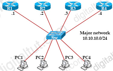
For example in the topology above suppose all of the gateways have the same priority and GLBP is turned on at the same time on all gateways (or they are configured with the preempt feature), R4 will be elected AVG because of its highest IP address 10.10.10.4. R3 will be elected SVG because of its second highest IP address (10.10.10.3). The AVFs are elected based on the weight so the four highest weight values would win for the four AVFs. In this case we only have four gateways so surely they are all elected AVFs. With GLBP, there is still one virtual IP address which is assigned by the administrator via the “glbp ip …” command (for example glbp 1 ip 10.10.10.100).
How GLBP works
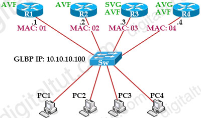
After the election ends, R4 is both the AVG and AVF; R3 is SVG and AVF; R2 & R1 are pure AVFs. R4 assigned the MAC addresses of 0007.b4000101, 0007.b4000102, 0007.b4000103, 0007.b4000104 to R1, R2, R3, R4 respectively; we will abbreviate the MAC addresses as 01, 02, 03 and 04. Let’s see how GLBP works!
The default gateway of PC1, PC2 and PC3 were set to 10.10.10.100 so if they want to send traffic outside they have to send ARP Request first to their default gateway. They broadcast an ARP Request to ask “Hey, I need to know the MAC address of the guy 10.10.10.100!”. R4, which is the AVG, is responsible for answering the ARP Request. But the trick here is it does not always give the same answer to that question:
For PC1, R4 will answer “The MAC address of the guy 10.10.10.100 is 01!”.
For PC2, R4 will answer “The MAC address of the guy 10.10.10.100 is 02!”.
For PC3, R4 will answer “The MAC address of the guy 10.10.10.100 is 03!”.
For PC4, R4 will answer “The MAC address of the guy 10.10.10.100 is 04!”.
As the result of this, PC1 will send the traffic to R1; PC2 will send traffic to R2; PC3 will send traffic to R3 and PC4 will send traffic to R4! And load balancing is achieved!
When AVG fails
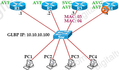
Everything is working smoothly then suddenly R4 (AVG) is down. What will happen now?
As we know R3 was chosen as SVG because of its second highest priority so when R4 is down, R3 becomes the new AVG and is responsible for forwarding traffic sent to the virtual MAC address of R4. In other words, R3 is now responsible for traffic from PC3 & PC4 with two MAC addresses 03, 04. Communication between R4 continues without disruption or change at the host side.
Wait! Maybe you have a question to ask here. So how about the Switch? How can the switch forward the frames to the new SVG on another port? Remember that Switch saved the MAC 04 for the port connecting to R4. Well, the answer here is when the standby becomes the active it will send a gratuitous ARP reply to flush the CAM tables of the switches and the ARP cache of the hosts. So the switch will learn the new port for MAC 04.
Each AVF listens to others, if one AVF can no more forward traffic, all listening AVFs will compete to take the responsibility of the failed AVF vMAC along with its own (AVF with higher weighting wins).
To detect a gateway failure, GLBP members communicate between each other through hello messages sent every 3 seconds to the multicast address 224.0.0.102, User Datagram Protocol (UDP) port 3222.
GLBP supports up to 1024 virtual routers (GLBP groups) per physical interface of a router.
Load balancing algorithm
GLBP load sharing is done in one of three ways:
Round-robin load-balancing algorithm: Each router MAC is used sequentially to respond to ARP requests. This is the default load balancing mode in GLBP and is suitable for any number of end hosts.
Weighted load-balancing algorithm: Traffic is balanced proportional to a configured weight. Each GLBP router in the group will advertise its weighting and assignment; the AVG will act based on that value. For example, if there are two routers in a group and R1 has double the forwarding capacity of router B, the weighting value of router A should be configured to be double the amount of R2.
Host-dependent load-balancing algorithm: A given host always uses the same router.
Interface Tracking
Like HSRP, GLBP can be configured to track interfaces. For example, if the WAN link from Router R4 is lost, GLBP detects the failure and decrements the router priority (when a tracked interface fails). The second router then becomes primary. This transition is transparent for the hosts.
![]()
GLBP Authentication
GLBP has three authentication types:
+ No authentication
+ MD5 authentication
+ Plain text authentication
MD5 is the most security method so far. With this method, the same keys are configured on both ends. One end will send the encrypted key (called hash, using MD5) to the other. At the other side, the same key is also encrypted and compared with the receiving encrypted key. If the two encrypted keys are the same then authentication is approved. The advantage of this method is only the encrypted key is sent through the link. The key for the MD5 hash can either be given directly in the configuration using a key string or supplied indirectly through a key chain.


“In fact, GLBP can run on both router and switch so the word “gateway”, which can represent for both router and switch, is better to describe GLBP.”
Do you mean a layer 3 switch? Or just any Cisco switch?
@Sky: We mean Layer 3 switch.
The gateway with the highest priority among the remaining ones is elected the Standby AVG (SVG) which will take the role of the AVG in the case it is down.
it should say the gateway with the second highest priority
@ROCKEY I believe its written correctly. If the 2nd highest priority as you say, then it would be R2 because the highest priority of the remaining ones is R3. And if R4 goes down, then SVG (R3) will take over, not R2.