
Wireless Questions 2
Question 1
Explanation
A prerequisite for configuring Mobility Groups is “All controllers must be configured with the same virtual interface IP address”. If all the controllers within a mobility group are not using the same virtual interface, inter-controller roaming may appear to work, but the handoff does not complete, and the client loses connectivity for a period of time. -> Answer B is correct.
Answer A is not correct because when the client moves to a different mobility group (with different mobility group name), that client would be connected (provided that the new connected controller had information about this client in its mobility list already) or drop (if the new connected controller have not had information about this client in its mobility list). For more information please read the note below.
Note:
A mobility group is a set of controllers, identified by the same mobility group name, that defines the realm of seamless roaming for wireless clients. By creating a mobility group, you can enable multiple controllers in a network to dynamically share information and forward data traffic when inter-controller or inter-subnet roaming occurs. Controllers in the same mobility group can share the context and state of client devices as well as their list of access points so that they do not consider each other’s access points as rogue devices.
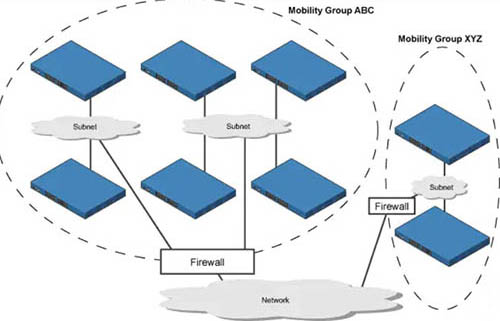
Let’s take an example:
The controllers in the ABC mobility group share access point and client information with each other. The controllers in the ABC mobility group do not share the access point or client information with the XYZ controllers, which are in a different mobility group. Therefore if a client from ABC mobility group moves to XYZ mobility group, and the new connected controller does not have information about this client in its mobility list, that client will be dropped.
Note: Clients may roam between access points in different mobility groups if the controllers are included in each other’s mobility lists.
Question 2
Explanation
As these wireless networks grow especially in remote facilities where IT professionals may not always be on site, it becomes even more important to be able to quickly identify and resolve potential connectivity issues ideally before the users complain or notice connectivity degradation.
To address these issues we have created Cisco’s Wireless Service Assurance and a new AP mode called “sensor” mode. Cisco’s Wireless Service Assurance platform has three components, namely, Wireless Performance Analytics, Real-time Client Troubleshooting, and Proactive Health Assessment. Using a supported AP or dedicated sensor the device can actually function much like a WLAN client would associating and identifying client connectivity issues within the network in real time without requiring an IT or technician to be on site.
Question 3
Explanation
Mobility, or roaming, is a wireless LAN client’s ability to maintain its association seamlessly from one access point to another securely and with as little latency as possible. Three popular types of client roaming are:
Intra-Controller Roaming: Each controller supports same-controller client roaming across access points managed by the same controller. This roaming is transparent to the client as the session is sustained, and the client continues using the same DHCP-assigned or client-assigned IP address.
Inter-Controller Roaming: Multiple-controller deployments support client roaming across access points managed by controllers in the same mobility group and on the same subnet. This roaming is also transparent to the client because the session is sustained and a tunnel between controllers allows the client to continue using the same DHCP- or client-assigned IP address as long as the session remains active.
Inter-Subnet Roaming: Multiple-controller deployments support client roaming across access points managed by controllers in the same mobility group on different subnets. This roaming is transparent to the client because the session is sustained and a tunnel between the controllers allows the client to continue using the same DHCP-assigned or client-assigned IP address as long as the session remains active.
Question 4
Explanation
The AP will attempt to resolve the DNS name CISCO-CAPWAP-CONTROLLER.localdomain. When the AP is able to resolve this name to one or more IP addresses, the AP sends a unicast CAPWAP Discovery Message to the resolved IP address(es). Each WLC that receives the CAPWAP Discovery Request Message replies with a unicast CAPWAP Discovery Response to the AP.
Question 5
Question 6
Explanation
These message logs inform that the radio channel has been reset (and the AP must be down briefly). With dynamic channel assignment (DCA), the radios can frequently switch from one channel to another but it also makes disruption. The default DCA interval is 10 minutes, which is matched with the time of the message logs. By increasing the DCA interval, we can reduce the number of times our users are disconnected for changing radio channels.
Question 7
Question 8
Question 9
Explanation
A Yagi antenna is formed by driving a simple antenna, typically a dipole or dipole-like antenna, and shaping the beam using a well-chosen series of non-driven elements whose length and spacing are tightly controlled.

Question 10
Explanation
Once you know the complete combination of transmitter power level, the length of cable, and the antenna gain, you can figure out the actual power level that will be radiated from the antenna. This is known as the effective isotropic radiated power (EIRP), measured in dBm.
EIRP is a very important parameter because it is regulated by governmental agencies in most countries. In those cases, a system cannot radiate signals higher than a maximum allowable EIRP. To find the EIRP of a system, simply add the transmitter power level to the antenna gain and subtract the cable loss.
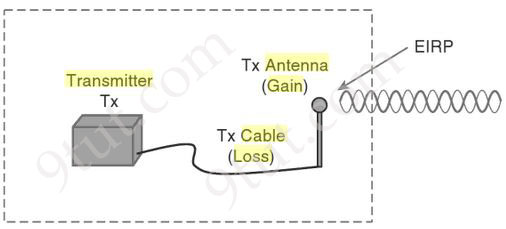
EIRP = Tx Power – Tx Cable + Tx Antenna
Suppose a transmitter is configured for a power level of 10 dBm (10 mW). A cable with 5-dB loss connects the transmitter to an antenna with an 8-dBi gain. The resulting EIRP of the system is 10 dBm – 5 dB + 8 dBi, or 13 dBm.
You might notice that the EIRP is made up of decibel-milliwatt (dBm), dB relative to an isotropic antenna (dBi), and decibel (dB) values. Even though the units appear to be different, you can safely combine them because they are all in the dB “domain”.
Reference: CCNA Wireless 640-722 Official Cert Guide


Help with this question please:
Which 2 methods are used to reduce the AP coverage area? (choose 2)
A. Reduce the transmit power
B. Increase minimum mandatory data rate
C. Reduce channel width from 40 Mhz to 20 Mhz
D. Enable Fastlane
E. Disable 2.4 Ghz and use only 5Ghz
Answers: A B
Are the answers correct? I could swear “E” was a correct answer.
@PiRaTa in the real world the issue with 5ghz having lower coverage is more to do with it being less able to penetrate obstacles like walls than it covering a smaller distance.
Q5 – A
Check the RADIUS Server Overwrite interface check box to enable the per-WLAN RADIUS source support. When enabled, the controller uses the interface specified on the WLAN configuration as identity and source for all RADIUS related traffic on that WLAN.
Or it would be C if:
When disabled, the controller uses the management interface as the identity in the NAS-IP-Address attribute.
https://www.cisco.com/c/en/us/td/docs/wireless/controller/8-2/config-guide/b_cg82/b_cg82_chapter_01100111.pdf