Search Results

Keyword: ‘ BGP for multiple protocols’

Border Gateway Protocol BGP Tutorial

digitaltut No comments

Basic understanding about BGP

We really want to show you why we need BGP first but it is very difficult to explain without understanding a bit about BGP. So we will learn some basic knowledge about BGP first.

First we need to understand the difference between Interior Gateway Protocol and Exterior Gateway Protocol, which is shown below:

IGP_EGP.jpg

Interior Gateway Protocol (IGP): A routing protocol operating within an Autonomous System (AS) like OSPF, EIGRP… Usually routers running IGP are under the same administration (of a company, corporation, individual)
Exterior Gateway Protocol (EGP): A routing protocol operating between different AS. BGP is the only EGP used nowadays

Read more…

BGP Questions 3

May 4th, 2014 digitaltut No comments

Here you will find answers to BGP Questions – Part 3

Question 1

Which option is true regarding the synchronization rule?

A. Do not use or internally advertise a route until the route is learned from a source other than BGP.
B. Do not use or advertise a route until the route is learned from a BGP peer.
C. Do not use or advertise routes marked PARTIAL.
D. Wait until a CONFIRM message is received before using routes from BGP neighbors.


Answer: A

Explanation

The complete synchronization rule is “A BGP router should not use, or advertise to an external neighbor, a route learned by IBGP, unless that route is local or is learned from the IGP.”

With the default of synchronization disabled, BGP can use and advertise to external BGP neighbors routes learned from an IBGP neighbor that are not present in the local routing table

The “synchronization” here means “synchronization between iBGP with its IGP (such as OSPF, EIGRP…)

You can disable synchronization if one of the following conditions is true:
Your AS does not pass traffic from one AS to another AS.
All the transit routers in your AS run BGP.


Note: BGP synchronization is disabled by default in Cisco IOS Software Release 12.2(8)T and later.

For more information about BGP Synchronization please read the explanation of Question 5 in this page. Also another good resource is : http://docwiki.cisco.com/wiki/Internetworking_Case_Studies_–_Using_the_Border_Gateway_Protocol_for_Interdomain_Routing#Synchronization

Question 2

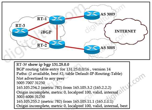
Refer to the exhibit. Router RT-1 and router RT-2 both advertise network 131.25.0.0/16 to router RT-3 via internal BGP. What is the reason that router RT-3 chose router RT-1 as its best path to network 131.25.0.0/16.

BGP_router_ID.jpg

A. It advertises the best AS-path.
B. It advertises the best origin code.
C. It advertises the best MED.
D. It advertises the best local preference.
E. It has a better router ID.
F. It advertises a lower autonomous system.


Answer: E

Explanation

Recall the route selection decision process in BGP:

Consider only (synchronized) routes with no AS loops and a valid next hop, and then:

Route selection decision process (from top to bottom) In this question…
Prefer highest weight (local to router) RT-3 is not an exit point
Prefer highest local preference (global within AS) same local preference of 100
Prefer route originated by the local router (next hop = 0.0.0.0) both routes are from IBGP
Prefer shortest AS path same
Prefer lowest origin code (IGP < EGP ) both are incomplete (EGP > IGP > Incomplete)
Prefer lowest MED (exchanged between autonomous systems) both MEDs are 0
Prefer EBGP path over IBGP path both are IBGP
Prefer the path through the closest IGP neighbor (IGP cost) not used because IBGPs are used
Prefer oldest route for EBGP paths. not used
Prefer the path with the lowest neighbor BGP router ID. the router-id 162.105.11.1 is lower than 165.105.3.2
Prefer the path with the lowest neighbor IP address.  

Question 3

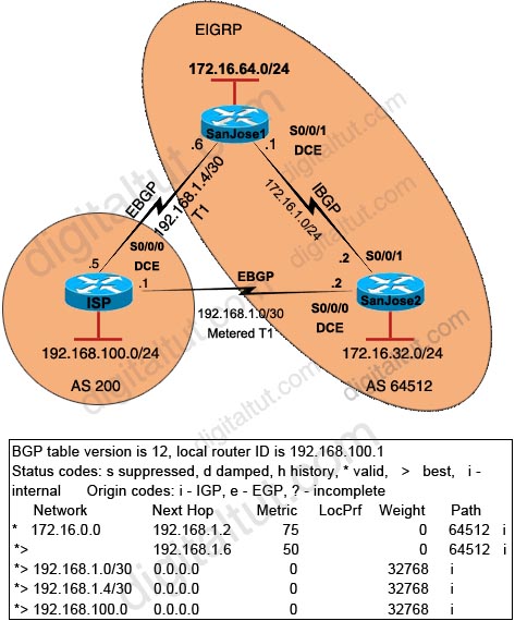
Refer to the exhibit. Router RT-1 chooses one path to network 198.133.219.0/24. Indicate the reason Router RT-1 chooses this “best” path.

BGP_Origin_Compare.jpg

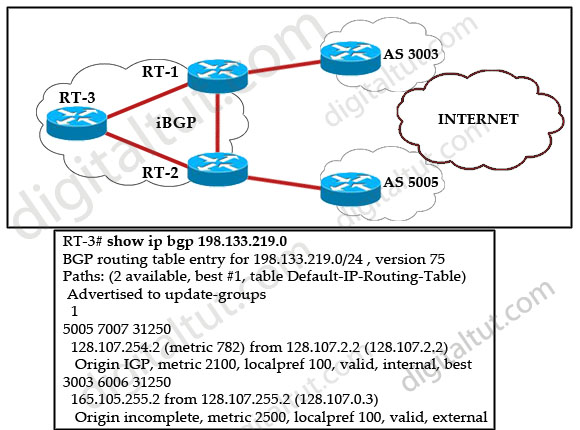
A. In making its decision about the best path, RT-1 gives precedence to the origin code.
B. In making its decision about the best path, RT-1 gives precedence to the BGP MED values.
C. IP address 128.107.2.2 is lower than 128.107.255.2.
D. In making its decision about the best path, RT-1 prefers the IGP metrics.
E. RT-1 prefers internal BGP routes.
F. IP address 128.107.254.2 is lower than 128.107.255.2.


Answer: A

Explanation

As explained in question 3, the IGP is preferred over incomplete.
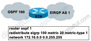
Question 4

The Border Gateway Protocol (BGP) is the core routing protocol of the Internet. Refer to the exhibit. Routers A and B are running BGP but the session is active. What command needs to be added to establish the BGP session?
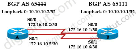
BGP_establish_session.jpg

hostname A
!
interface loopback 0
ip address 10.10.10.2 255.255.255.255
!
interface serial 0/0
ip address 172.16.10.2 255.255.255.252
!
interface serial 0/1
ip address 172.16.10.5 255.255.255.252
!
router bgp 65444
neighbor 10.10.10.1 remote-as 65111
neighbor 10.10.10.1 update-source loopback 0
neighbor 10.10.10.1 ebgp-multihop

A. ip route 10.10.10.1 255.255.255.255 s0/0
ip route 10.10.10.1 255.255.255.255 s0/ 1
B. no synchronization
C. network 10.10.10.0
D. neighbor 10.10.10.1 next-hop-self


Answer: A

Explanation

In this case we want to achieve load balancing so the loopback interface must be used to establish neighborship.

If we check the routing table of router A, we will see that there is no entry for the remote network 1.1.1.1/32 -> router A does not know how to reach the loopback interface on router B -> a TCP session can’t be established to router B. Therefore we need to tell router A a way to reach router B.

(Reference and a good resource: http://www.cisco.com/en/US/tech/tk365/technologies_tech_note09186a00800c95bb.shtml)

Question 5

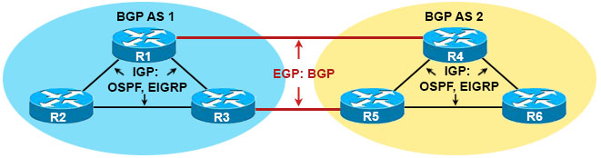
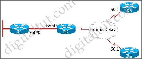
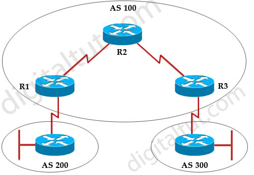
Refer to the exhibit. Autonomous systems 200 and 300 have EBGP sessions established with their directly connected routers in autonomous system 100. IGP has been configured on all routers in autonomous system 100 and they successfully exchange routing updates. Traffic originated in autonomous system 200 cannot reach the destination autonomous system 300. What configuration should be done on the routers in autonomous system 100 in order for the traffic coming from autonomous system 200 to be forwarded to autonomous system 300?

BGP_IBGP_synchronization.jpg

A. IBGP session must be established between routers R1 and R3, and the synchronization must be turned on.
B. IBGP session must be established between routers R1 and R3, and the synchronization must be turned off.
C. IBGP session must be established between routers R1 R2 and R2 R3. and the synchronization must be turned on.
D. IBGP session must be established between routers R1 R2 and R2 R3, and the synchronization must be turned off.
E. IBGP speakers within autonomous 100 must be fully meshed, and the synchronization must be turned on.
F. IBGP speakers within autonomous 100 must be fully meshed, and the synchronization must be turned off.


Answer: F

Explanation

The synchronization rule states that if an AS provides transit service to another AS, BGP should not advertise a route until all of the routers within the AS have learned about the route via an IGP. To understand why this rule exists, let’s take an example if this rule is not there.

BGP_IBGP_synchronization_Example.jpg

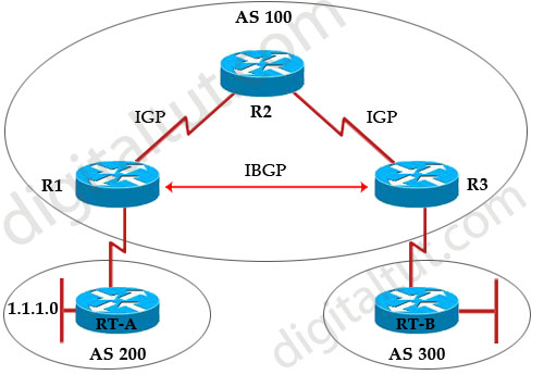
Suppose Rt-A wants RT-B to access its local LAN 1.1.1.0, so it advertises this network through R1. R1 and R3 are running IBGP so R1 sends this update to R3 through R2 (using the next-hop-self to use its own interface’s IP address). In turn, R3 announces to RT-B that it can reach 1.1.1.0 via R3.

Now Rt-B really wants to send traffic to 1.1.1.0 so it will send to R3. R3 does a look up and sees that the network can be reachable via R1. It then does a lookup for R1’s IP address and sees that it is reachable via R2 -> so it forwards packets to R2. But R2, running IGP (like OSPF), does not find an entry for 1.1.1.0 so R2 drops all the packets for that network – a black-hole is created!

That is why the BGP synchronization rule is born. With this rule, when R3 receives an advertisement for 1.1.1.0 from R1, it adds that route to its BGP table and before sending advertisement to RT-B, it first checks its IGP routing table to see whether an entry exists for that route. In this example, R3’s IGP routing table does not know how to reach 1.1.1.0 so R3 will not advertise this network to RT-B. This route is only advertised to RT-B when IGP makes an entry in the routing table for 1.1.1.0.

Well, now you understand the importance of BGP Synchronization rule but now I wish to explain why this rule causes trouble in fully-meshed IBGP!

BGP_IBGP_synchronization_fully-messed.jpg

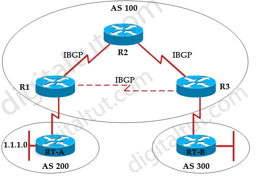
Synchronization prevents fully-meshed IBGP from working properly. Because no IGP is running so R3 cannot advertise any route to RT-B even if no black-hole exists in this topology.

Note: A “fully-meshed” can be a physical fully-meshed topology or a topology where all routers in the same AS established IBGP connections with each other (although they do not need to be directly connected). So in the topology above, the connection between R1 & R3 is represented by a dashed line, which means it can be physically connected or not (but an IBGP connection must be established on both routers).

Therefore if all routers in AS 100 is fully-meshed, the synchronization rule must be turned off -> F is correct.

Question 6

Which one of the following statements about BGP is FALSE?

A. BGP uses TCP port 179.
B. BGP ensures reliability of updates by using the reliable transport services of TCP.
C. The network command with the mask option never installs a prefix into the BGP table unless there is a matching prefix exists in the IP route table.
D. A TCP connection is required before exchanging updates.
E. BGP uses notification and the update messages to establish and maintain the BGP neighbor relationship.


Answer: E

Explanation

An underlying connection between two BGP speakers is established before any routing information is exchanged. This connection takes place on TCP port 179.

Unlike other routing protocols, the router must be manually configured with the neighbor information on both sides of the connection -> E is correct (which is FALSE in this question)

Question 7

Which BGP option is required when load sharing over multiple equal-bandwidth parallel links from a single CE router to a single ISP router over eBGP?

A. eBGP Multipath
B. eBGP Multihop
C. BGP Synchronization
D. Public AS numbers


Answer: B

Explanation

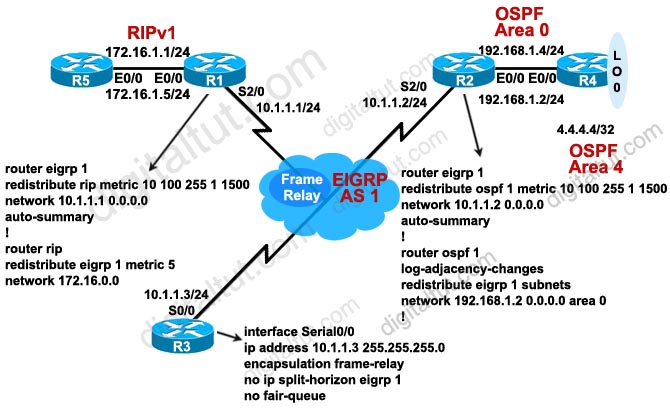
The eBGP multihop allows a neighbor connection between two external peers that do not have direct connection. The multihop is only for eBGP and not for iBGP. For example, in the topology below router A wants to establish neighbor relationship with the loopback0 of router B (to allow load balancing), which does not have direct connection so it must use “ebgp-multihop”

BGP_ebgp-multihop.jpg

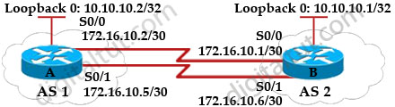
For your reference, the full configurations of both router A & B are shown below:

A# int loopback 0
ip address 10.10.10.2 255.255.255.255
router bgp 1
neighbor 10.10.10.1 remote-as 2
neighbor 10.10.10.1 ebgp-multihop
neighbor 10.10.10.1 update-source loopback 0
network 10.10.10.2 mask 255.255.255.255
ip route 10.10.10.1 255.255.255.255 172.16.10.1
ip route 10.10.10.1 255.255.255.255 172.16.10.6
B# int loopback 0
ip address 10.10.10.1 255.255.255.255
router bgp 2
neighbor 10.10.10.2 remote-as 1
neighbor 10.10.10.2 ebgp-multihop
neighbor 10.10.10.2 update-source loopback 0
network 10.10.10.1 mask 255.255.255.255
ip route 10.10.10.2 255.255.255.255 172.16.10.2
ip route 10.10.10.2 255.255.255.255 172.16.10.5

Note: If router B wants to establish neighbor relationship with the directly connected interface of router A, it only needs these commands:

B#
router bgp 2
neighbor 172.16.10.2 remote-as 1

But notice the traffic from router B would be sent to 172.16.10.2 interface only and load balancing would not take place.

(Reference: http://www.cisco.com/en/US/tech/tk365/technologies_tech_note09186a00800c95bb.shtml)

Question 8

Which statement is true about IBGP routers?

A. They must be fully meshed.
B. They can be in a different AS.
C. They must be directly connected,
D. They do not need to be directly connected.


Answer: D

Question 9

Refer to the exhibit. On the basis of the configuration that is provided, how would the BGP updates that come from router R1 be replicated inside autonomous system 65200?

BGP_no_synchronization.jpg

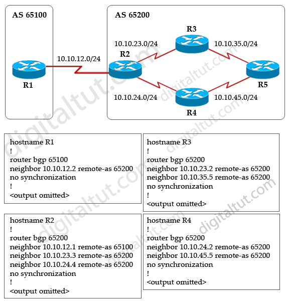
A. All BGP updates that are received on router R2 will be sent to routers R3 and R4. Routers R3 and R4 will then forward those BGP updates to router R5.
B. All BGP updates that are received on router R2 will not be sent to routers R3 and R4.
C. All BGP updates that are received on router R2 will be sent directly to router R5.
D. None of the BGP updates that are received on router R2 will ever be received by router R5.


Answer: D

Explanation

All BGP updates that are received on router R2 will be sent to routers R3 and R4 but R3 & R4 will not forward those BGP updates to R5. This is called the BGP split-horizon rule (which states that a route learned from one IBGP neighbor will not be advertised to another IBGP neighbor) -> A is not correct.

The BGP updates received on router R2 will be sent to R3 and R4 without violating the BGP split-horizon rule because R2 receives updates from an EBGP (R1), not IBGP -> B is not correct.

From the configuration of R2, we learn that R2 did not establish neighbor relationship with R5 so they are not neighbors -> no BGP updates will be sent from R2 to R5 -> C is not correct.

The BGP split-horizon rule prevents updates received on R2 from being sent to R5 -> D is correct.

Question 10

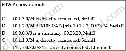
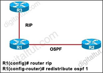
The 192.168.0.0 network is not being propagated throughout the network. Observe the BGP configuration commands from the advertising router. What is the reason the 192.168.0.0 route is not being advertised?

router bgp 65111
neighbor 172.16.1.1 remote-as 65111
neighbor 172.16.2.1 remote-as 65112
network 192.168.0.0
network 10.0.0.0
!
ip route 192.168.0.0 255.255.0.0 null0

A. The network 192.168.0.0 statement is missing mask 255.255.0.0
B. The network 192.168.0.0 statement is missing mask 0.0.255.255.
C. The network 10.0.0.0 statement is missing mask 255.0.0.0.
D. The network 10.0.0.0 statement is missing mask 0.255.255.255.
E. The auto-summary configuration is missing.


Answer: A

Explanation

The “network” statement in other routing protocols (EIGRP, OSPF, RIP…) is used to enable routing protocol on the interfaces within that “network” statement. But in BGP, the function of a network statement is to tell the router to search the IP routing table for a particular network, and if that network is found, originate it into the BGP database. But notice that you must have an exact match in the IP routing table to appear the network in the BGP routing table (in this case we don’t see the auto-summary command so we suppose it is disabled in this case). For example:
+ network 10.10.10.0/8 will appear in BGP if network 10.10.10.0/8 appears in the IP routing table.
+ network 10.10.10.0/24 will appear in BGP if network 10.10.10.0/24 appears in the IP routing table.

Therefore, in this question the static route “ip route 192.168.0.0 255.255.0.0 null0” was used to put a route to 192.168.0.0/16 into the routing table (although it points to Null0 but this command really makes that route appears in the routing table). But the “network 192.168.0.0” statement tells the router to lookup network 192.168.0.0/24 (if the network statement under BGP-mode does not specify a subnet mask, the default subnet mask of that class will be used). The router only finds network 192.168.0.0/16 -> The network 192.168.0.0 is not being propagated throughout the network because of the mismatch of the subnet mask -> A is correct.

Just for your information, in fact we have to suppose there is no entry of the network 192.168.0.0/24 exist in the routing table except the static route “ip route 192.168.0.0 255.255.0.0 null0”. If such an entry exists (for example, a directly connected entry like “C 192.168.0.0/24 is directly connected”) then the router still advertises it with the “network 192.168.0.0” (without mask 255.255.0.0) command.

ENCOR FAQs & Tips

November 16th, 2023 digitaltut 218 comments

In this article, I will try to summarize all the Frequently Asked Questions in the ENCOR 350-401 v1.1 Exam. Hope it will save you some time searching through the Internet and asking your friends & teachers.

1. Please tell me how many questions in the real ENCOR exam, and how much time to answer them?

You have 120 minutes to answer 102 questions, include multiple choice and drag drop questions. There are some lab sims (from 3 to 4) in this exam currently. But if your native language is not English, Cisco allows you a 30-minute exam time extension. But there are a few requirements to get this extension, so the best way is asking your teacher or mentor before taking the exam.

2. How much does the ENCOR 350-401 cost? And how many points I need to pass the exam?

This exam costs $400. You need at least 825/1000 points to pass this exam. But you will no longer see your exam score after your test. You will only see if you passed or failed as well as details on each section performance (in percent). Sometimes you will see the status remains “Score Pending” and you have to wait for a few days (up to 72 business hours) in order for the PearsonVUE portal to reflect your actual score (“Pass” or “Fail”).

3. I passed the ENCOR exam, will I get a CCNP certificate for it?

No, ENCOR is only the core exam of the CCNP Enterprise certification. In order to get the CCNP Enterprise certification, you need to pass the ENCOR exam and one of the following concentration exams:
– 300-410 ENARSI: Implementing Cisco Enterprise Advanced Routing and Services (ENARSI)
– 300-415 ENSDWI: Implementing Cisco SD-WAN Solutions (ENSDWI)
– 300-420 ENSLD: Designing Cisco Enterprise Networks (ENSLD)
– 300-425 ENWLSD: Designing Cisco Enterprise Wireless Networks (ENWLSD)
– 300-430 ENWLSI: Implementing Cisco Enterprise Wireless Networks (ENWLSI)
– 300-435 ENAUTO: Implementing Automation for Cisco Enterprise Solutions (ENAUTO)

For example, you need to pass the ENCOR and ENARSI exam to get the CCNP Enterprise certificate.

4. So which concentration exam should I choose to complete my CCNP Enterprise cert?

First you should understand each of the concentration exams above:

– In ENARSI exam you will learn more about routing (EIGRP, OSPF, BGP, VPN & VRF-Lite) and services  (DHCP, AAA, SNMP, uRPF, IP SLA, NetFlow), mainly about how to troubleshoot them.
– In ENSDWI exam you will learn mainly about Cisco SD-WAN architecture (about vBond, vSmart, vManage and vEdge) and how they work. If your company is using them or you have a special reason to know about them then you should learn this exam.
– In ENSLD exam you will learn how to design popular routing protocols, WAN; describe SD-Access and SD-WAN.
– Two exams ENWLSD and ENWLSI will teach you about Wireless in detail
– The ENAUTO exam allows you to learn how to program and automate your network with APIs (JSON, XML, YANG; NETCONF and RESTCONF) using Python. The “network” here includes IOS XE devices, Cisco DNA Center, Cisco SD-WAN and Cisco Meraki.

In the above exams, only the ENARSI exam teach you about “traditional” network. If you don’t have any special reason to learn other exams then it is the most suitable exam for you. If you used to learn how to program/code then the ENAUTO is also a recommended exam to take.

If you are still in doubt about any exam then we recommend you to find the syllabus of that exam and have a closer look by yourself before deciding, just google it (with keyword: “syllabus” + that exam name). We don’t post direct links here because the subjects of these exams may change in the future so we wish you to find the latest syllabuses of these exams.

5. In the real exam, I clicked “Next” after choosing the answer, can I go back for reviewing?

No, you can’t go back so you can’t re-check your answers after clicking the “Next” button.

6. What are your recommended materials for ENCOR?

There are many options you can choose, but below are materials used and recommended by many candidates:

Recommended Books

Video training

  • CBT Nuggets
  • INE

Simulator (all are free)

  • GNS3 – the best simulator for learning ROUTE
  • Packet Tracer
  • EVE-NG

7. Are the exam questions the same in all the geographical locations?

Yes, the exam questions are the same in all geographical locations. But notice that Cisco has a pool of questions and each time you take the exam, a number of random questions will show up so you will not see all the same questions as the previous exam.

8. I passed the ENCOR exam. Do you have any site similar for CCNP Enterprise exams?

We have certprepare.com for CCNP Enterprise ENSDWI (a concentration exam of CCNP Enterprise certification) and networktut.com for ENARSI (another concentration exam of CCNP Enterprise certification).

We also have other sites (but only for sharing experience) like voicetut.com for Voice/Collaboration track, securitytut.com for Security track, dctut.com for Data Center track, sptut.com for Service Provider track, wirelesstut.com for Wireless track, opstut.com for DevNet track. Hope you enjoy these sites and find useful information too!

9. How many CCNP tracks does Cisco support now?

Cisco supports 7 CCNP tracks, which are:

1. CCNP Enterprise
2. CCNP Security
3. CCNP Service provider
4. CCNP Collaboration
5. CCNP Data Center
6. Cisco Certified DevNet
7. Cisco Certified CyberOps

In each track, you need to pass a dedicated core exam then pass one concentration exam of that track. Please check the picture below for more detail:

Cisco_Next_Level_Certification_Path.jpg

Note: With these new tracks, CCNA is no longer a prerequisite for CCNP. You can go directly for CCNP certs. But the knowledge of CCNA is highly recommended if you want to reach CCNP.

10. I passed (old) CCNP but my CCNP cert is going to expire and I want to recertify it. Which exam should I get?

According to Cisco Recertification Policy page, you need to complete one of the following things:

– Pass one technology core exam
– Pass any two professional concentration exams
– Pass one CCIE lab exam

Therefore if you only want to take one exam to recertify then you must pass the ENCOR 350-401 exam or any technology core exam of other tracks (for example the DCCOR 350-601 of Data Center track or the SCOR 350-701 of Security track).

Also if you earn 80 CE credits then you can also recertify your CCNP Enterprise cert.

Is there anything you want to ask? Just ask! All of us will help you.

SD-WAN & SD-Access Solutions

February 6th, 2021 digitaltut 38 comments

SD-Access Quick summary

There are five basic device roles in the fabric overlay:
+ Control plane node: This node contains the settings, protocols, and mapping tables to provide the endpoint-to-location (EID-to-RLOC) mapping system for
the fabric overlay.
+ Fabric border node: This fabric device (for example, core layer device) connects external Layer 3 networks to the SDA fabric.
+ Fabric edge node: This fabric device (for example, access or distribution layer device) connects wired endpoints to the SDA fabric.
+ Fabric WLAN controller (WLC): This fabric device connects APs and wireless endpoints to the SDA fabric.
+ Intermediate nodes: These are intermediate routers or extended switches that do not provide any sort of SD-Access fabric role other than underlay services.

SD_Access_Fabric.jpg

Three major building blocks that make up SDA: the control plane, the data plane and the policy plane.

+ Control-Plane based on LISP
+ Data-Plane based on VXLAN
+ Policy-Plane based on TrustSec

SD-WAN Quick Summary

The primary components for the Cisco SD-WAN solution consist of the vManage network management system (management plane), the vSmart controller (control plane), the vBond orchestrator (orchestration plane), and the vEdge router (data plane).

+ vManage – This centralized network management system provides a GUI interface to easily monitor, configure, and maintain all Cisco SD-WAN devices and links in the underlay and overlay network.

+ vSmart controller – This software-based component is responsible for the centralized control plane of the SD-WAN network. It establishes a secure connection to each vEdge router and distributes routes and policy information via the Overlay Management Protocol (OMP), acting as a route reflector. It also orchestrates the secure data plane connectivity between the vEdge routers by distributing crypto key information, allowing for a very scalable, IKE-less architecture.

+ vBond orchestrator – This software-based component performs the initial authentication of vEdge devices and orchestrates vSmart and vEdge connectivity. It also has an important role in enabling the communication of devices that sit behind Network Address Translation (NAT).

+ vEdge router – This device, available as either a hardware appliance or software-based router, sits at a physical site or in the cloud and provides secure data plane connectivity among the sites over one or more WAN transports. It is responsible for traffic forwarding, security, encryption, Quality of Service (QoS), routing protocols such as Border Gateway Protocol (BGP) and Open Shortest Path First (OSPF), and more.

SD_WAN_Physical_Architecture.jpg

Cisco SD-WAN uses Overlay Management Protocol (OMP) which manages the overlay network. OMP runs between the vSmart controllers and WAN Edge routers (and among vSmarts themselves) where control plane information, such as the routing, policy, and management information, is exchanged over a secure connection.

VPNs in SD-WAN

In the SD-WAN overlay, virtual private networks (VPNs) provide segmentation. Each VPN is equivalent to a VRF, which is isolated from one another and have their own forwarding tables. An interface or subinterface is explicitly configured under a single VPN and cannot be part of more than one VPN. Devices attached to an interface in one VPN cannot communicate with devices in another VPN unless policy is put in place to allow it. The VPN ranges from 0 to 65535, but several VPNs are reserved for internal use.

The Transport & Management VPNs

There are two implicitly configured VPNs in the WAN Edge devices and controllers: VPN 0 and VPN 512.

VPN 0 is the transport VPN. It contains all the interfaces that connect to the WAN links. Secure DTLS/TLS connections to the controllers are initiated from this VPN. Static or default routes or a dynamic routing protocol needs to be configured inside this VPN in order to get appropriate next-hop information so the control plane can be established and IPsec tunnel traffic can reach remote sites.

VPN 0 connects the WAN Edge to the WAN transport and creates control plane and data plane connections. The WAN Edge device can connect to multiple WAN transport(s) on different interfaces on the same VPN 0 transport segment. At least one interface needs to be configured to initially reach the SD-WAN controllers for onboarding.

VPN 512 is the management VPN. It carries the out-of-band management traffic to and from the Cisco SD-WAN devices. This VPN is ignored by OMP and not carried across the overlay network.

SDWAN_VPNs.jpg

Question 1

Explanation

There are five basic device roles in the fabric overlay:
+ Control plane node: This node contains the settings, protocols, and mapping tables to provide the endpoint-to-location (EID-to-RLOC) mapping system for
the fabric overlay.
+ Fabric border node: This fabric device (for example, core layer device) connects external Layer 3 networks to the SDA fabric.
+ Fabric edge node: This fabric device (for example, access or distribution layer device) connects wired endpoints to the SDA fabric.
+ Fabric WLAN controller (WLC): This fabric device connects APs and wireless endpoints to the SDA fabric.
+ Intermediate nodes: These are intermediate routers or extended switches that do not provide any sort of SD-Access fabric role other than underlay services.

SD_Access_Fabric.jpg

Reference: CCNP and CCIE Enterprise Core ENCOR 350-401 Official Cert Guide

Question 2

Explanation

+ Orchestration plane (vBond) assists in securely onboarding the SD-WAN WAN Edge routers into the SD-WAN overlay (-> Therefore answer A mentioned about vBond). The vBond controller, or orchestrator, authenticates and authorizes the SD-WAN components onto the network. The vBond orchestrator takes an added responsibility to distribute the list of vSmart and vManage controller information to the WAN Edge routers. vBond is the only device in SD-WAN that requires a public IP address as it is the first point of contact and authentication for all SD-WAN components to join the SD-WAN fabric. All other components need to know the vBond IP or DNS information.

+ Management plane (vManage) is responsible for central configuration and monitoring. The vManage controller is the centralized network management system that provides a single pane of glass GUI interface to easily deploy, configure, monitor and troubleshoot all Cisco SD-WAN components in the network. (-> Answer C and answer D are about vManage)

+ Control plane (vSmart) builds and maintains the network topology and make decisions on the traffic flows. The vSmart controller disseminates control plane information between WAN Edge devices, implements control plane policies and distributes data plane policies to network devices for enforcement (-> Answer B is about vSmart)

Question 3

Explanation

The southbound protocol used by APIC is OpFlex that is pushed by Cisco as the protocol for policy enablement across physical and virtual switches.

Southbound interfaces are implemented with some called Service Abstraction Layer (SAL), which talks to the network elements via SNMP and CLI.

Note: Cisco OpFlex is a southbound protocol in a software-defined network (SDN).

Question 4

Explanation

Today the Dynamic Network Architecture Software Defined Access (DNA-SDA) solution requires a fusion router to perform VRF route leaking between user VRFs and Shared-Services, which may be in the Global routing table (GRT) or another VRF. Shared Services may consist of DHCP, Domain Name System (DNS), Network Time Protocol (NTP), Wireless LAN Controller (WLC), Identity Services Engine (ISE), DNAC components which must be made available to other virtual networks (VN’s) in the Campus.

Reference: https://www.cisco.com/c/en/us/support/docs/cloud-systems-management/dna-center/213525-sda-steps-to-configure-fusion-router.html

Question 5

Explanation

Fabric mode APs continue to support the same wireless media services that traditional APs support; apply AVC, quality of service (QoS), and other wireless policies; and establish the CAPWAP control plane to the fabric WLC. Fabric APs join as local-mode APs and must be directly connected to the fabric edge node switch to enable fabric registration events, including RLOC assignment via the fabric WLC. The fabric edge nodes use CDP to recognize APs as special wired hosts, applying special port configurations and assigning the APs to a unique overlay network within a common EID space across a fabric. The assignment allows management simplification by using a single subnet to cover the AP infrastructure at a fabric site.

Reference: https://www.cisco.com/c/en/us/td/docs/solutions/CVD/Campus/sda-sdg-2019oct.html

Question 6

Explanation

The tunneling technology used for the fabric data plane is based on Virtual Extensible LAN (VXLAN). VXLAN encapsulation is UDP based, meaning that it can be forwarded by any IP-based network (legacy or third party) and creates the overlay network for the SD-Access fabric. Although LISP is the control plane for the SD-Access fabric, it does not use LISP data encapsulation for the data plane; instead, it uses VXLAN encapsulation because it is capable of encapsulating the original Ethernet header to perform MAC-in-IP encapsulation, while LISP does not. Using VXLAN allows the SD-Access fabric to support Layer 2 and Layer 3 virtual topologies (overlays) and the ability to operate over any IP-based network with built-in network segmentation (VRF instance/VN) and built-in group-based policy.

Reference: CCNP and CCIE Enterprise Core ENCOR 350-401 Official Cert Guide

Question 7

Explanation

Access Points
+ AP is directly connected to FE (or to an extended node switch)
+ AP is part of Fabric overlay

Reference: https://www.ciscolive.com/c/dam/r/ciscolive/us/docs/2018/pdf/BRKEWN-2020.pdf

Question 8

Explanation

The primary components for the Cisco SD-WAN solution consist of the vManage network management system (management plane), the vSmart controller (control plane), the vBond orchestrator (orchestration plane), and the vEdge router (data plane).

+ vManage – This centralized network management system provides a GUI interface to easily monitor, configure, and maintain all Cisco SD-WAN devices and links in the underlay and overlay network.

+ vSmart controller – This software-based component is responsible for the centralized control plane of the SD-WAN network. It establishes a secure connection to each vEdge router and distributes routes and policy information via the Overlay Management Protocol (OMP), acting as a route reflector. It also orchestrates the secure data plane connectivity between the vEdge routers by distributing crypto key information, allowing for a very scalable, IKE-less architecture.

+ vBond orchestrator – This software-based component performs the initial authentication of vEdge devices and orchestrates vSmart and vEdge connectivity. It also has an important role in enabling the communication of devices that sit behind Network Address Translation (NAT).

+ vEdge router – This device, available as either a hardware appliance or software-based router, sits at a physical site or in the cloud and provides secure data plane connectivity among the sites over one or more WAN transports. It is responsible for traffic forwarding, security, encryption, Quality of Service (QoS), routing protocols such as Border Gateway Protocol (BGP) and Open Shortest Path First (OSPF), and more.

Reference: https://www.cisco.com/c/dam/en/us/td/docs/solutions/CVD/SDWAN/CVD-SD-WAN-Design-2018OCT.pdf

Question 9

Question 10

Explanation

There are five basic device roles in the fabric overlay:
+ Control plane node: This node contains the settings, protocols, and mapping tables to provide the endpoint-to-location (EID-to-RLOC) mapping system for the fabric overlay.
+ Fabric border node: This fabric device (for example, core layer device) connects external Layer 3 networks to the SDA fabric.
+ Fabric edge node: This fabric device (for example, access or distribution layer device) connects wired endpoints to the SDA fabric.
+ Fabric WLAN controller (WLC): This fabric device connects APs and wireless endpoints to the SDA fabric.
+ Intermediate nodes: These are intermediate routers or extended switches that do not provide any sort of SD-Access fabric role other than underlay services.

SD_Access_Fabric.jpg

Reference: CCNP and CCIE Enterprise Core ENCOR 350-401 Official Cert Guide

Switching Mechanism Questions

February 4th, 2021 digitaltut 13 comments

Packet Switching

Packet Switching is the method of moving a packet from a router’s input interface to an output interface. There are three main packet switching methods: Process Switching, Fast Switching and Cisco Express Forwarding (CEF).

Process switching is the oldest and slowest switching methods because it must examines the routing table, determines which interface the packet should be switched to and then switches the packet for every coming packet. The router CPU is responsible of choosing the appropriate process to handle the packet and scheduling the running of the process. With this kind of switching, it was clear that the router could not handle packets fast enough to attain the speeds needed as the traffic flows were increasing at a rapid pace across the networks. So an idea was born to solve this problem: Why not cache the results of the IP next-hop and layer 2 look-ups and use them to switch the next packet towards a given destination? This concept gave birth to fast switching.

Fast Switching relies on the idea of caching the routing decision of first packet (via process switching) then applying to the next ones without calculating. The first packet is copied to packet memory, and if the destination network is found in fast switching cache, the frame is rewritten and sent to outgoing interface. If the destination address is not present in the fast-switching cache, the packet is returned to process switching path, where the processor attempts to build a cache entry which can be used to forward packets to the destination.

CEF switching is a Cisco proprietary and advanced Layer3 IP switching mechanism that was designed to tackle the deficiencies associated with fast-switching. CEF optimizes performance, scalability, and resiliency for large and complex networks with dynamic traffic patterns. CEF’s retrieval and packet forwarding technique is less CPU intensive than process or fast switching. This results in higher throughput when CEF is enabled.

CEF Quick summary

Cisco Express Forwarding (CEF) provides the ability to switch packets through a device in a very quick and efficient way while also keeping the load on the router’s processor low. CEF is made up of two different main components: the Forwarding Information Base (FIB) and the Adjacency Table. These are automatically updated at the same time as the routing table.

The adjacency table is tasked with maintaining the layer 2 next-hop information for the FIB.

RIB vs FIB

Each routing protocol like OSPF, EIGRP has its own Routing information base (RIB) and they select their best candidates to try to install to global RIB so that it can then be selected for forwarding. In order to view the RIB table, use the command “show ip ospf database” for OSPF, “show ip eigrp topology” for EIGRP or “show ip bgp” for BGP. To view the Forwarding Information Base (FIB), use the “show ip cef” command. RIB is in Control plane while FIB is in Data plane.

The Forwarding Information Base (FIB) contains destination reachability information as well as next hop information. This information is then used by the router to make forwarding decisions. The FIB allows for very efficient and easy lookups. Below is an example of the FIB table:

show_ip_cef.jpg

The FIB maintains next-hop address information based on the information in the IP routing table (RIB). In other words, FIB is a mirror copy of RIB.

RIB is in Control plane (and it is not used for forwarding) while FIB is in Data plane (and it is used for forwarding).

Question 1

Explanation

Cisco Express Forwarding (CEF) provides the ability to switch packets through a device in a very quick and efficient way while also keeping the load on the router’s processor low. CEF is made up of two different main components: the Forwarding Information Base (FIB) and the Adjacency Table. These are automatically updated at the same time as the routing table.

The Forwarding Information Base (FIB) contains destination reachability information as well as next hop information. This information is then used by the router to make forwarding decisions. The FIB allows for very efficient and easy lookups. Below is an example of the FIB table:

show_ip_cef.jpg

The adjacency table is tasked with maintaining the layer 2 next-hop information for the FIB. An example of the adjacency table is shown below:

show_adjacency.jpg

Note: A fast cache is only used when fast switching is enabled while CEF is disabled.

Question 2

Explanation

Cisco IOS software basically supports two modes of CEF load balancing: On per-destination or per-packet basis.

For per destination load balancing a hash is computed out of the source and destination IP address (-> Answer E is correct). This hash points to exactly one of the adjacency entries in the adjacency table (-> Answer D is correct), providing that the same path is used for all packets with this source/destination address pair. If per packet load balancing is used the packets are distributed round robin over the available paths. In either case the information in the FIB and adjacency tables provide all the necessary forwarding information, just like for non-load balancing operation.

The number of paths used is limited by the number of entries the routing protocol puts in the routing table, the default in IOS is 4 entries for most IP routing protocols with the exception of BGP, where it is one entry. The maximum number that can be configured is 6 different paths -> Answer A is not correct.

Reference: https://www.cisco.com/en/US/products/hw/modules/ps2033/prod_technical_reference09186a00800afeb7.html

Question 3

Explanation

The Forwarding Information Base (FIB) table – CEF uses a FIB to make IP destination prefix-based switching decisions. The FIB is conceptually similar to a routing table or information base. It maintains a mirror image of the forwarding information contained in the IP routing table. When routing or topology changes occur in the network, the IP routing table is updated, and these changes are reflected in the FIB. The FIB maintains next-hop address information based on the information in the IP routing table.

Reference: https://www.cisco.com/c/en/us/support/docs/routers/12000-series-routers/47321-ciscoef.html

Question 4

Explanation

CEF uses a Forwarding Information Base (FIB) to make IP destination prefix-based switching decisions. The FIB is conceptually similar to a routing table or information base. It maintains a mirror image of the forwarding information contained in the IP routing table. When routing or topology changes occur in the network, the IP routing table is updated, and those changes are reflected in the FIB. The FIB maintains next-hop address information based on the information in the IP routing table. Because there is a one-to-one correlation between FIB entries and routing table entries, the FIB contains all known routes and eliminates the need for route cache maintenance that is associated with earlier switching paths such as fast switching and optimum switching.

Note: In order to view the Routing information base (RIB) table, use the “show ip route” command. To view the Forwarding Information Base (FIB), use the “show ip cef” command. RIB is in Control plane while FIB is in Data plane.

Question 5

Explanation

Both answer A and answer C in this question are correct. It is hard to say which correct answer is better.

Question 6

Explanation

“Punt” is often used to describe the action of moving a packet from the fast path (CEF) to the route processor for handling.

Cisco Express Forwarding (CEF) provides the ability to switch packets through a device in a very quick and efficient way while also keeping the load on the router’s processor low. CEF is made up of two different main components: the Forwarding Information Base (FIB) and the Adjacency Table.

Process switching is the slowest switching methods (compared to fast switching and Cisco Express Forwarding) because it must find a destination in the routing table. Process switching must also construct a new Layer 2 frame header for every packet. With process switching, when a packet comes in, the scheduler calls a process that examines the routing table, determines which interface the packet should be switched to and then switches the packet. The problem is, this happens for the every packet.

Reference: http://www.cisco.com/web/about/security/intelligence/acl-logging.html

Question 7

Explanation

The Forwarding Information Base (FIB) contains destination reachability information as well as next hop information. This information is then used by the router to make forwarding decisions. The FIB allows for very efficient and easy lookups. Below is an example of the FIB table:

show_ip_cef.jpg

The FIB maintains next-hop address information based on the information in the IP routing table (RIB).

Note: In order to view the Routing information base (RIB) table, use the “show ip route” command. To view the Forwarding Information Base (FIB), use the “show ip cef” command. RIB is in Control plane while FIB is in Data plane.

Virtualization Questions

February 3rd, 2021 digitaltut 34 comments

Virtualization Quick Summary

A virtual machine (VM) is a software emulation of a physical server with an operating system. From an application’s point of view, the VM provides the look and feel of a real physical server, including all its components, such as CPU, memory, and network interface cards (NICs).

A hypervisor, also known as a virtual machine monitor, is a software that creates and manages virtual machines. A hypervisor allows one physical server to support multiple guest VMs by virtually sharing its resources, such as memory and processing.

There are two types of hypervisors: type 1 and type 2 hypervisor.

In type 1 hypervisor (or native hypervisor), the hypervisor is installed directly on the physical server. Then instances of an operating system (OS) are installed on the hypervisor. Type 1 hypervisor has direct access to the hardware resources. Therefore they are more efficient than hosted architectures. Some examples of type 1 hypervisor are VMware vSphere/ESXi, Oracle VM Server, KVM and Microsoft Hyper-V.

In contrast to type 1 hypervisor, a type 2 hypervisor (or hosted hypervisor) runs on top of an operating system and not the physical hardware directly. A big advantage of Type 2 hypervisors is that management console software is not required. Examples of type 2 hypervisor are VMware Workstation (which can run on Windows, Mac and Linux) or Microsoft Virtual PC (only runs on Windows).

Type1_Type2_Hypervisors_detail.jpg

Comparison Type 1 and Type 2 hypervisors

  Type 1 hypervisor Type 2 hypervisor
Other name Bare metal hypervisor Hosted hypervisor
Runs on Underlying physical host machine hardware Underlying operating system (host OS)
Best suited for Large, resource-intensive, or fixed-use workloads Desktop and development environments
Can negotiate dedicated resources? Yes No
Knowledge required System administrator-level knowledge Basic user knowledge
Examples VMware ESXi, Microsoft Hyper-V, KVM Oracle VM VirtualBox, VMware Workstation, Microsoft Virtual PC

Structure of virtualization in a hypervisor

Hypervisors provide virtual switch (vSwitch) that Virtual Machines (VMs) use to communicate with other VMs on the same host. The vSwitch may also be connected to the host’s physical NIC to allow VMs to get layer 2 access to the outside world.

Each VM is provided with a virtual NIC (vNIC) that is connected to the virtual switch. Multiple vNICs can connect to a single vSwitch, allowing VMs on a physical host to communicate with one another at layer 2 without having to go out to a physical switch.


Virtual_machine_structure.jpg

Although vSwitch does not run Spanning-tree protocol but vSwitch implements other loop prevention mechanisms. For example, a frame that enters from one VMNIC is not going to go out of the physical host from a different VMNIC card.

Benefits of Virtualizing

Server virtualization and the use of virtual machines is profoundly changing data center dynamics. Most organizations are struggling with the cost and complexity of hosting multiple physical servers in their data centers. The expansion of the data center, a result of both scale-out server architectures and traditional “one application, one server” sprawl, has created problems in housing, powering, and cooling large numbers of underutilized servers. In addition, IT organizations continue to deal with the traditional cost and operational challenges of matching server resources to organizational needs that seem fickle and ever changing.

Virtual machines can significantly mitigate many of these challenges by enabling multiple application and operating system environments to be hosted on a single physical server while maintaining complete isolation between the guest operating systems and their respective applications. Hence, server virtualization facilitates server consolidation by enabling organizations to exchange a number of underutilized servers for a single highly utilized server running multiple virtual machines.

By consolidating multiple physical servers, organizations can gain several benefits:
+ Underutilized servers can be retired or redeployed.
+ Rack space can be reclaimed.
+ Power and cooling loads can be reduced.
+ New virtual servers can be rapidly deployed.
+ CapEx (higher utilization means fewer servers need to be purchased) and OpEx (few servers means a simpler environment and lower maintenance costs) can be reduced.

Para-virtualization

Para-virtualization is an enhancement of virtualization technology in which a guest operating system (guest OS) is modified prior to installation inside a virtual machine. This allows all guest OS within the system to share resources and successfully collaborate, rather than attempt to emulate an entire hardware environment. The modification also decreases the execution time required to complete operations that can be problematic in virtual environments.

Paravirtualization.jpg

By granting the guest OS access to the underlying hardware, Para-virtualization enables communication between the guest OS and the hypervisor (using API calls), thus improving performance and efficiency within the system. This is the main difference between Para-virtualization and (traditional) full-virtualization.

Question 1

Explanation

There is nothing special with the configuration of Gi0/0 on R1. Only Gi0/0 interface on R2 is assigned to VRF VPN_A. The default VRF here is similar to the global routing table concept in Cisco IOS

Question 2

Explanation

Answer C and answer D are not correct as only route distinguisher (RD) identifies the customer routing table and “allows customers to be assigned overlapping addresses”.

Answer A is not correct as “When BGP is configured, route targets are transmitted as BGP extended communities”

Question 3

Explanation

In VRF-Lite, Route distinguisher (RD) identifies the customer routing table and allows customers to be assigned overlapping addresses. Therefore it can support multiple customers with overlapping addresses -> Answer E is correct.

VRFs are commonly used for MPLS deployments, when we use VRFs without MPLS then we call it VRF lite -> Answer C is not correct.

– VRF-lite does not support IGRP and ISIS. ( -> Answer B is not correct)
– The capability vrf-lite subcommand under router ospf should be used when configuring OSPF as the routing protocol between the PE and the CE.
– VRF-lite does not affect the packet switching rate. (-> Answer A is not correct)

Reference: https://www.cisco.com/c/en/us/td/docs/switches/lan/catalyst4500/12-2/25ew/configuration/guide/conf/vrf.html#wp1045190

Question 4

Explanation

There are two types of hypervisors: type 1 and type 2 hypervisor.

In type 1 hypervisor (or native hypervisor), the hypervisor is installed directly on the physical server. Then instances of an operating system (OS) are installed on the hypervisor. Type 1 hypervisor has direct access to the hardware resources. Therefore they are more efficient than hosted architectures. Some examples of type 1 hypervisor are VMware vSphere/ESXi, Oracle VM Server, KVM and Microsoft Hyper-V.

In contrast to type 1 hypervisor, a type 2 hypervisor (or hosted hypervisor) runs on top of an operating system and not the physical hardware directly. A big advantage of Type 2 hypervisors is that management console software is not required. Examples of type 2 hypervisor are VMware Workstation (which can run on Windows, Mac and Linux) or Microsoft Virtual PC (only runs on Windows).

Type1_Type2_Hypervisors.jpg

Question 5

Explanation

Server virtualization and the use of virtual machines is profoundly changing data center dynamics. Most organizations are struggling with the cost and complexity of hosting multiple physical servers in their data centers. The expansion of the data center, a result of both scale-out server architectures and traditional “one application, one server” sprawl, has created problems in housing, powering, and cooling large numbers of underutilized servers. In addition, IT organizations continue to deal with the traditional cost and operational challenges of matching server resources to organizational needs that seem fickle and ever changing.

Virtual machines can significantly mitigate many of these challenges by enabling multiple application and operating system environments to be hosted on a single physical server while maintaining complete isolation between the guest operating systems and their respective applications. Hence, server virtualization facilitates server consolidation by enabling organizations to exchange a number of underutilized servers for a single highly utilized server running multiple virtual machines.

By consolidating multiple physical servers, organizations can gain several benefits:
+ Underutilized servers can be retired or redeployed.
+ Rack space can be reclaimed.
+ Power and cooling loads can be reduced.
+ New virtual servers can be rapidly deployed.
+ CapEx (higher utilization means fewer servers need to be purchased) and OpEx (few servers means a simpler environment and lower maintenance costs) can be reduced.

Reference: https://www.cisco.com/c/en/us/solutions/collateral/data-center-virtualization/net_implementation_white_paper0900aecd806a9c05.html

Question 6

Explanation

A virtual machine (VM) is a software emulation of a physical server with an operating system. From an application’s point of view, the VM provides the look
and feel of a real physical server, including all its components, such as CPU, memory, and network interface cards (NICs).

The virtualization software that creates VMs and performs the hardware abstraction that allows multiple VMs to run concurrently is known as a hypervisor.

There are two types of hypervisors: type 1 and type 2 hypervisor.

In type 1 hypervisor (or native hypervisor), the hypervisor is installed directly on the physical server. Then instances of an operating system (OS) are installed on the hypervisor. Type 1 hypervisor has direct access to the hardware resources. Therefore they are more efficient than hosted architectures. Some examples of type 1 hypervisor are VMware vSphere/ESXi, Oracle VM Server, KVM and Microsoft Hyper-V.

In contrast to type 1 hypervisor, a type 2 hypervisor (or hosted hypervisor) runs on top of an operating system and not the physical hardware directly. A big advantage of Type 2 hypervisors is that management console software is not required. Examples of type 2 hypervisor are VMware Workstation (which can run on Windows, Mac and Linux) or Microsoft Virtual PC (only runs on Windows).

Type1_Type2_Hypervisors.jpg

Question 7

Question 8

Explanation

Because some PE routers might receive routing information they do not require, a basic requirement is to be able to filter the MP-iBGP updates at the ingress to the PE router so that the router does not need to keep this information in memory.

The Automatic Route Filtering feature fulfills this filtering requirement. This feature is available by default on all PE routers, and no additional configuration is necessary to enable it. Its function is to filter automatically VPN-IPv4 routes that contain a route target extended community that does not match any of the PE’s configured VRFs. This effectively discards any unwanted VPN-IPv4 routes silently, thus reducing the amount of information that the PE has to store in memory -> Answer D is correct.

Reference: MPLS and VPN Architectures Book, Volume 1

The reason that PE1 dropped the route is there is no “route-target import 999:999” command on PE1 (so we see the “DENIED due to:extended community not supported” in the debug) so we need to type this command to accept this route -> Answer E is correct.

Question 9

Explanation

Broadcast radiation refers to the processing that is required every time a broadcast is received on a host. Although IP is very efficient from a broadcast perspective when compared to traditional protocols such as Novell Internetwork Packet Exchange (IPX) Service Advertising Protocol (SAP), virtual machines and the vswitch implementation require special consideration. Because the vswitch is software based, as broadcasts are received the vswitch must interrupt the server CPU to change contexts to enable the vswitch to process the packet. After the vswitch has determined that the packet is a broadcast, it copies the packet to all the VMNICs, which then pass the broadcast packet up the stack to process. This processing overhead can have a tangible effect on overall server performance if a single domain is hosting a large number of virtual machines.

Note: This overhead effect is not a limitation of the vswitch implementation. It is a result of the software-based nature of the vswitch embedded in the ESX hypervisor.

Reference: https://www.cisco.com/c/en/us/solutions/collateral/data-center-virtualization/net_implementation_white_paper0900aecd806a9c05.html

—————————————————————-

Note about the structure of virtualization in a hypervisor:

Hypervisors provide virtual switch (vSwitch) that Virtual Machines (VMs) use to communicate with other VMs on the same host. The vSwitch may also be connected to the host’s physical NIC to allow VMs to get layer 2 access to the outside world.

Each VM is provided with a virtual NIC (vNIC) that is connected to the virtual switch. Multiple vNICs can connect to a single vSwitch, allowing VMs on a physical host to communicate with one another at layer 2 without having to go out to a physical switch.


Virtual_machine_structure.jpg

Although vSwitch does not run Spanning-tree protocol but vSwitch implements other loop prevention mechanisms. For example, a frame that enters from one VMNIC is not going to go out of the physical host from a different VMNIC card.

Question 10

Explanation

A bare-metal hypervisor (Type 1) is a layer of software we install directly on top of a physical server and its underlying hardware. There is no software or any operating system in between, hence the name bare-metal hypervisor. A Type 1 hypervisor is proven in providing excellent performance and stability since it does not run inside Windows or any other operating system. These are the most common type 1 hypervisors:

+ VMware vSphere with ESX/ESXi
+ KVM (Kernel-Based Virtual Machine)
+ Microsoft Hyper-V
+ Oracle VM
+ Citrix Hypervisor (formerly known as Xen Server)

DMVPN Questions

July 31st, 2019 digitaltut 44 comments

Note: If you are not sure about DMVPN, please read our DMVPN tutorial first.

Question 1

Explanation

From the output we learn that the logical address 10.2.1.2 is mapped to the NBMA address 10.12.1.2. Type “dynamic” means NBMA address was obtained from NHRP Request packet. Type “static” means NBMA address is statically configured. The “authoritative” flag means that the NHRP information was obtained from the Next Hop Server (NHS).

Reference: http://www.cisco.com/c/en/us/td/docs/ios/12_4/ip_addr/configuration/guide/hadnhrp.html

Question 2

Explanation

When DMVPN tunnels flap, check the neighborship between the routers as issues with neighborship formation between routers may cause the DMVPN tunnel to flap. In order to resolve this problem, make sure the neighborship between the routers is always up.

Reference: http://www.cisco.com/c/en/us/support/docs/security-vpn/ipsec-negotiation-ike-protocols/29240-dcmvpn.html#Prblm1

Question 3

Explanation

DMVPN is not a protocol, it is the combination of the following technologies:

+ Multipoint GRE (mGRE)
+ Next-Hop Resolution Protocol (NHRP)
+ Dynamic Routing Protocol (EIGRP, RIP, OSPF, BGP…) (optional)
+ Dynamic IPsec encryption (optional)
+ Cisco Express Forwarding (CEF)

For more information about DMVPN, please read our DMVPN tutorial.

Question 4

Explanation

To allow communication to multiple sites using only one tunnel interface, we need to configure that tunnel in “multipoint” mode. Otherwise we have to create many tunnel interfaces, each can only communicate to one site.

DMVPN_Topo_mGRE.jpg


Question 5

Explanation

An mGRE tunnel inherits the concept of a classic GRE tunnel but an mGRE tunnel does not require a unique tunnel interface for each connection between Hub and spoke like traditional GRE. One mGRE can handle multiple GRE tunnels at the other ends. Unlike classic GRE tunnels, the tunnel destination for a mGRE tunnel does not have to be configured; and all tunnels on Spokes connecting to mGRE interface of the Hub can use the same subnet.

DMVPN_Topo_mGRE.jpg

For more information about DMVPN, please read our DMVPN tutorial.

Question 6

Explanation

GRE tunnels are the first thing we have to configure to create a DMVPN network so we should start troubleshooting from there. NHRP can only work properly with operating GRE tunnels.

Question 7

Question 8

Explanation

The “show crypto isakmp sa” command displays all current Internet Key Exchange (IKE) security associations (SAs) at a peer.

QM_IDLE state means this tunnel is UP and the IKE SA key exchange was successful, but is idle and may be used for subsequent quick mode exchanges. It is in a quiescent state (QM) -> Answers A, C, D are incorrect so answer B is the only suitable answer left.

Question 9

Explanation

The DMVPN is comprised of IPsec/GRE tunnels that connect branch offices to the data center. DMVPN troubleshooting requires the network engineer to verify neighbor links, routing and VPN peer connectivity. The GRE protocol is required to support routing advertisements. The VPN peer connection is comprised of IKE and IPsec security association exchanges.

The command “show crypto ipsec sa” is used to verify IPsec connectivity between branch office and data center router. We can also use this command to display the statistics of an active tunnel on a DMVPN network.

DMVPN_show_crypto_ipsec_sa.jpg

Note:
+ The command “show crypto isakmp sa” is used on DMVPN to verify IKE connectivity status to branch offices. The normal IKE state = QM IDLE for branch routers and data center routers.
+ The command “show crypto engine connection active” displays the total encrypts and decrypts per SA.

Reference: http://www.cisco.com/c/en/us/support/docs/security-vpn/ipsec-negotiation-ike-protocols/29240-dcmvpn.html

Question 10

Question 11

Question 12

Explanation

Both DMVPN Phase 2 and phase 3 support spoke to spoke communications (spokes talk to each other directly). In this case there is only an option of phase 2 (not phase 3) so it is the only correct answer.

Question 13

Explanation

Some documents say RIPv2 also supports DMVPN but EIGPR, OSPF and BGP are the better choices so we should choose them.

Question 14

Explanation

DMVPN is not a protocol, it is the combination of the following technologies:
+ Multipoint GRE (mGRE)
+ Next-Hop Resolution Protocol (NHRP)
+ Dynamic Routing Protocol (EIGRP, RIP, OSPF, BGP…) (optional)
+ Dynamic IPsec encryption (optional)
+ Cisco Express Forwarding (CEF)

DMVPN combines multiple GRE (mGRE) Tunnels, IPSec encryption and NHRP (Next Hop Resolution Protocol) to perform its job and save the administrator the need to define multiple static crypto maps and dynamic discovery of tunnel endpoints.

Question 15

EVN & VRF Questions

July 21st, 2019 digitaltut 56 comments

Quick review:

Easy Virtual Network (EVN) is an IP-based network virtualization solution that helps enable network administrators to provide traffic separation and path isolation on a shared network infrastructure. EVN uses existing Virtual Route Forwarding (VRF)-Lite technology to:
+ Simplify Layer 3 network virtualization
+ Improve shared services support
+ Enhance management, troubleshooting, and usability

Question 1

Explanation

All the subinterfaces and associated EVNs have the same IP address assigned. In other words, a trunk interface is identified by the same IP address in different EVN contexts. EVN automatically generates subinterfaces for each EVN. For example, both Blue and Green VPN Routing and Forwarding (VRF) use the same IP address of 10.0.0.1 on their trunk interface:

vrf definition Blue
vnet tag 100
vrf definition Green
vnet tag 200
!
interface gigabitethernet0/0/0
vnet trunk
ip address 10.0.0.1 255.255.255.0

-> A is correct.

In fact answer B & C are not correct because each EVN has separate routing table and forwarding table.

Note: The combination of the VPN IP routing table and the associated VPN IP forwarding table is called a VPN routing and forwarding (VRF) instance.

Question 2

Explanation

EVN is supported on any interface that supports 802.1q encapsulation, for example, an Ethernet interface. Instead of adding a new field to carry the VNET tag in a packet, the VLAN ID field in 802.1q is repurposed to carry a VNET tag. The VNET tag uses the same position in the packet as a VLAN ID. On a trunk interface, the packet gets re-encapsulated with a VNET tag. Untagged packets carrying the VLAN ID are not EVN packets and could be transported over the same trunk interfaces.

Reference: http://www.cisco.com/c/en/us/products/collateral/ios-nx-os-software/layer-3-vpns-l3vpn/whitepaper_c11-638769.html

Question 3

Explanation

An example of using “autonomous-system {autonomous-system-number}” command is shown below:

router eigrp 100
address-family ipv4 vrf Cust
net 192.168.12.0
autonomous-system 100
no auto-summary

This configuration is performed under the Provide Edge (PE) router to run EIGRP with a Customer Edge (CE) router. The “autonomous-system 100” command indicates that the EIGRP AS100 is running between PE & CE routers.

Question 4

Question 5

Question 6

Explanation

EVN builds on the existing IP-based virtualization mechanism known as VRF-Lite. EVN provides enhancements in path isolation, simplified configuration and management, and improved shared service support

Reference: http://www.cisco.com/c/en/us/td/docs/ios-xml/ios/evn/configuration/xe-3s/evn-xe-3s-book/evn-overview.html

Maybe the “improved shared services support” term here implies about the support of sharing between different VRFs (through route-target, MP-BGP)

Question 7

Explanation

This question is not clear because we have to configure a static route pointing to the global routing table while it stated that “all interfaces are in the same VRF”. But we should understand both outside and inside interfaces want to ping the loopback interface.

Question 8

Explanation

EVN supports IPv4, static routes, Open Shortest Path First version 2 (OSPFv2), and Enhanced Interior Gateway Routing Protocol (EIGRP) for unicast routing, and Protocol Independent Multicast (PIM) and Multicast Source Discovery Protocol (MSDP) for IPv4 Multicast routing. EVN also supports Cisco Express Forwarding (CEF) and Simple Network Management Protocol (SNMP).

Reference: http://www.cisco.com/c/en/us/td/docs/ios-xml/ios/evn/configuration/xe-3s/evn-xe-3s-book/evn-overview.html

Question 9

Explanation

Route-target is is tagged to each VPN when it is exported. In other words, when a prefix is exported with a route-target, an extended BGP community is attached to that prefix. If this community is matched with the (import) route-target of the receiving side then the prefix is imported to the receiving VRF.

Question 10

Explanation

Easy Virtual Network (EVN) is an IP-based virtualization technology that provides end-to-end virtualization of two or more Layer-3 networks. You can use a single IP infrastructure to provide separate virtual networks whose traffic paths remain isolated from each other.

An EVN trunk interface connects VRF-aware routers together and provides the core with a means to transport traffic for multiple EVNs. Trunk interfaces carry tagged traffic. The tag is used to de-multiplex the packet into the corresponding EVN. A trunk interface has one subinterface for each EVN. The vnet trunk command is used to define an interface as an EVN trunk interface.

In other words, EVN trunk interfaces allow multiple VRFs to use the same physical interfaces for transmission but the data of each VRF is treated separately. Without EVN trunk interfaces we need to create many subinterfaces. Therefore virtual network trunk (VNET) decreases the network configuration required.

Note: There is no “Easy Trunk” component or technology.

Drag and Drop

July 7th, 2019 digitaltut 85 comments

Question 1

Explanation

NAT64 provides communication between IPv6 and IPv4 hosts by using a form of network address translation (NAT). NAT64 requires a dedicated prefix, called NAT64 prefix, to recognize which hosts need IPv4-IPv6 translation. NAT64 prefix can be a Network-specific prefix (NSP), which is configured by a network administrator, or a well-known prefix (which is 64:FF9B::/96). When a NAT64 router receives a packet which starts with NAT64 prefix, it will proceed this packet with NAT64.

NAT64 is not as simple as IPv4 NAT which only translates source or destination IPv4 address. NAT64 translates nearly everything (source & destination IP addresses, port number, IPv4/IPv6 headers… which is called a session) from IPv4 to IPv6 and vice versa. So NAT64 “modifies session during translation”.

Question 2

Explanation

The order of the BGP states is: Idle -> Connect -> (Active) -> OpenSent -> OpenConfirm -> Established

+ Idle: No peering; router is looking for neighbor. Idle (admin) means that the neighbor relationship has been administratively shut down.
+ Connect: TCP handshake completed.
+ Active: BGP tries another TCP handshake to establish a connection with the remote BGP neighbor. If it is successful, it will move to the OpenSent state. If the ConnectRetry timer expires then it will move back to the Connect state. Note: Active is not a good state.
+ OpenSent: An open message was sent to try to establish the peering.
+ OpenConfirm: Router has received a reply to the open message.
+ Established: Routers have a BGP peering session. This is the desired state.

Reference: http://www.ciscopress.com/articles/article.asp?p=1565538&seqNum=3

Question 3

Explanation

The Challenge Handshake Authentication Protocol (CHAP) verifies the identity of the peer by means of a three-way handshake. These are the general steps performed in CHAP:
1) After the LCP (Link Control Protocol) phase is complete, and CHAP is negotiated between both devices, the authenticator sends a challenge message to the peer.
2) The peer responds with a value calculated through a one-way hash function (Message Digest 5 (MD5)).
3) The authenticator checks the response against its own calculation of the expected hash value. If the values match, the authentication is successful. Otherwise, the connection is terminated.

This authentication method depends on a “secret” known only to the authenticator and the peer. The secret is not sent over the link. Although the authentication is only one-way, you can negotiate CHAP in both directions, with the help of the same secret set for mutual authentication.

Reference: http://www.cisco.com/c/en/us/support/docs/wan/point-to-point-protocol-ppp/25647-understanding-ppp-chap.html

For more information about CHAP challenge please read our PPP tutorial.

Question 5

Explanation

AAA offers different solutions that provide access control to network devices. The following services are included within its modular architectural framework:
+ Authentication – The process of validating users based on their identity and predetermined credentials, such as passwords and other mechanisms like digital certificates. Authentication controls access by requiring valid user credentials, which are typically a username and password. With RADIUS, the ASA supports PAP, CHAP, MS-CHAP1, MS-CHAP2, that means Authentication supports encryption.
+ Authorization – The method by which a network device assembles a set of attributes that regulates what tasks the user is authorized to perform. These attributes are measured against a user database. The results are returned to the network device to determine the user’s qualifications and restrictions. This database can be located locally on Cisco ASA or it can be hosted on a RADIUS or Terminal Access Controller Access-Control System Plus (TACACS+) server. In summary, Authorization controls access per user after users authenticate.
+ Accounting – The process of gathering and sending user information to an AAA server used to track login times (when the user logged in and logged off) and the services that users access. This information can be used for billing, auditing, and reporting purposes.

Question 6

Question 7

Question 8

Explanation

NAT64 provides communication between IPv6 and IPv4 hosts by using a form of network address translation (NAT). There are two different forms of NAT64, stateless and stateful:

+ Stateless NAT64: maps the IPv4 address into an IPv6 prefix. As the name implies, it keeps no state. It does not save any IP addresses since every v4 address maps to one v6 address. Stateless NAT64 does not conserve IP4 addresses.
+ Stateful NAT64 is a stateful translation mechanism for translating IPv6 addresses to IPv4 addresses, and IPv4 addresses to IPv6 addresses. Like NAT44, it is called stateful because it creates or modifies bindings or session state while performing translation (1:N translation). It supports both IPv6-initiated and IPv4-initiated communications using static or manual mappings. Stateful NAT64 converses IPv4 addresses.

NPTv6 stands for Network Prefix Translation. It’s a form of NAT for IPv6 and it supports one-to-one translation between inside and outside addresses

Question 9

Question 10

Question 11

Question 12

Question 13

OSPF Questions 3

May 6th, 2014 digitaltut 1 comment

Here you will find answers to OSPF Questions – Part 3

Question 1

Refer to the exhibit. You are the network administrator responsible for the NProuter, the 10.1.1.1 router, and the 10.1.1.2 router. What can you determine about the OSPF operations from the debug output?

NProuter#debug ip ospf events

OSPF events debugging is on

NProuter#
00:02:03: OSPF: Rev hello from 172.16.1.1 area 0 from Serial0/0 10.1.1.1
00:02:03: OSPF: Mismatched hello parameter from 10.1.1.1
00:02:03: OSPF: Dead R 120 C 10, Hello R 30 C 30
00:02:26: OSPF’ Rcv hello from 192.168.1.2 area 0 from Serial0/0 10.1.1.2
00:02:26: OSPF: Mismatched hello parameters from 10.1.1.2
00:02:26: OSPF: Dead R 120 C 10, Hello R 30 C 30

A. The NProuter has two OSPF neighbors in the “Full” adjacency state.
B. The NProuter serial0/0 interface has the OSPF dead timer set to 10 seconds.
C. The NProuter serial0/0 interface has been configured with an OSPF network type of “point-to-point”.
D. The 10.1.1.1 and 10.1.1.2 routers are not using the default OSPF dead and hello timers setting.
E. The “Mismatched” error is caused by the expiration of the OSPF timers.


Answer: B

Explanation

First we should understand clearly about the line

Dead R 120 C 10, Hello R 30 C 30

The “R” here means “Received” and “C” means “Configured”. In other words, “Dead R” is the Dead Timer Received from the neighbor and the “Dead C” is the Dead Timer of the local router.

Therefore in this case “Dead R 120 C 10” means the Death Timer of the neighbor is 120 seconds while the local Dead Timer is 10 seconds, which causes a mismatch. Also we can learn that the local OSPF dead timer is set to 10 seconds -> B is correct.

For your information, by default, OSPF uses a 10-second hello timer and 40-second hold timer on broadcast and point-to-point links, and a 30-second hello timer and 120-second hold timer for all other network types. So we can’t confirm answer D is correct or not.

Question 2

You have just completed an OSPF implementation. While executing your verification plan, you determine that R1 is not able to establish full OSPF adjacency with R2. The show ip ospf neighbor command output on R1 shows that R2 is stuck in the INIT state.

What could be the cause of this problem?

A. DR and BDR election errors between R1 and R2.
B. The R2 router has not received the OSPF hello packets from the R1 router.
C. Mismatched interface maximum transmission unit (MTU) configuration between the R1 and R2.
D. Mismatched OSPF hello interval configuration between the R1 and R2.
E. Corrupted LSAs exchanges between the R1 and R2.


Answer: B

Explanation

When a router receives an OSPF Hello from a neighbor, it sends the Hello packet by including that neighbor’s router ID in the Hello packet. If the neighbor does not receive this packet (means that it doesn’t see itself in this packet), it will be stuck in INIT state. INIT state can be understood as a one-way Hello. An example of a router stuck in INIT state is shown below:

show_ip_ospf_neighbor_INIT_state.jpg

Question 3

Refer to the exhibit. You have completed an OSPF implementation, and you are verifying OSPF operation. You notice that router A and router B are stuck in the two-way state. From the show ip ospf interface command output, what is the cause of this issue?

OSPF_show_ip_ospf_interface.jpg

A. All OSPF implementations must have at least one interface in area 0.
B. You are attempting to run in the broadcast mode over an NBMA interface.
C. Both routers are configured to function as a BDR; therefore, there is no DR router.
D. Someone has changed the OSPF router ID; therefore you must clear the OSPF process.
E. The OSPF priority is set to 0 on both routers; therefore neither can become the DR.


Answer: E

Explanation

When OSPF adjacency is formed, a router goes through several state changes before it becomes fully adjacent with its neighbor. The states are Down, Attempt, Init, 2-Way, Exstart, Exchange, Loading, and Full.

An OSPF neighbor reaches the 2-way state when bidirectional communication is established (each router has seen the other’s hello packet). This is the beginning of an OSPF adjacency. On broadcast media and non-broadcast multiaccess networks, the DR and BDR are elected in this state. But the priority on both routers are 0 so no DR and BDR are elected -> These routers stay in the 2-way state.

(Reference and a good resource of OSPF Neighbor states: http://www.cisco.com/en/US/tech/tk365/technologies_tech_note09186a0080093f0e.shtml)

Question 4

You have completed an OSPF implementation, and you are verifying OSPF operation. During this verification, you notice that the OSPF route of 172.16.10.0 is repeatedly appearing and disappearing from the routing table. Further investigation finds that the OSPF CPU utilization is very high and the routers are constantly performing SPF calculations. You determine that 172.16.20.2 is the source of the 172.16.10.0 route. Using the show ip ospf database router 172.16.20.1 command, you notice that when this show command is performed repeatedly, the contents of the LSA change every few seconds.

What could be the cause of this problem?

A. OSPF authentication errors between some of the routers.
B. Two routers have the same OSPF router ID.
C. Issues with mistuned OSPF timers.
D. OSPF LSA pacing issues between some of the routers.
E. OSPF neighbor adjacency problems between some of the routers.


Answer: B

Question 5

The maximum number of routers per OSPF area typically depends on which three factors? (Choose three)

A. the kind of OSPF areas being implemented
B. the number of external LSAs in the network
C. the number of DRs and BDRs in the areas
D. the number of virtual links in the areas
E. how well the areas can be summarized
F. the use of LSA filters


Answer: A B E

Explanation

The maximum number of routers per area depends on several factors, including the following:
+ What kind of area do you have?
+ What kind of CPU power do you have in that area?
+ What kind of media?
+ Will you be running OSPF in NBMA mode?
+ Is your NBMA network meshed?
+ Do you have a lot of external LSAs in the network?
+ Are other areas well summarized?

For this reason, it’s difficult to specify a maximum number of routers per area. Consult your local sales or system engineer for specific network design help.

(Reference: http://www.cisco.com/en/US/tech/tk365/technologies_white_paper09186a0080094e9e.shtml#t40)

Question 6

When verifying OSPF virtual link problems, which is an important item to check on the two transit OSPF routers?

A. OSPF process ID
B. OSPF router ID
C. OSPF network type
D. OSPF memory usage
E. OSPF CPU utilization
F. OSPF stub area configurations


Answer: B

Explanation

The OSPF router IDs of the two transit OSPF routers are used to form the virtual link (with the area area-id virtual-link neighbor-router-id command) so it is an important item to check -> B is correct.

Question 7

The administrator wants to verify the current state of the OSPF database loading process.
Which show command should the administrator use?

A. show ip ospf [process-id] interface
B. show ip ospf neighbor
C. show ip ospf [process-id]
D. show ip ospf [process-id area-id] database


Answer: B

Explanation

The “show ip ospf neighbor” command can be used to view the current state of the OSPF database loading process. In the output below we can see router 2.2.2.2 is in 2way state, router 3.3.3.3 is elected as the BDR & router 4.4.4.4 is the BR.

show_ip_ospf_neighbor_OSPF_database_loading.jpg

Question 8

Which two statements about route redistribution when implementing OSPF are true? (Choose two)

A. Routes learned using any IP routing protocol can only be redistributed into non IP routing protocols.
B. OSPF can import routes learned using EIGRP, RIP, and IS-IS.
C. OSPF routes cannot be exported into EIGRP, RIP, and IS-IS.
D. At the interdomain level, OSPF cannot import routes learned using BGP.
E. OSPF routes can be exported into BGP.


Answer: B E

Question 9

An administrator types in the command router ospf 1 and receives the error message: “OSPF process 1 cannot start.” (Output is omitted.)
What should be done to correctly set up OSPF?

A. Ensure that an interface has been configured with an IP address.
B. Ensure that an interface has been configured with an IP address and is up.
C. Ensure that IP classless is enabled.
D. Ensure that the interfaces can ping their directly connected neighbors.


Answer: B

Explanation

OSPF can be only started when there is at least one interface up and configured with an IP address on the router.

Question 10

Which three are advantages to creating multiple areas in OSPF? (Choose three)

A. less frequent SPF calculations
B. fewer hello packets
C. smaller routing tables
D. reduced LSU overhead
E. fewer adjacencies needed


Answer: A C D

Explanation

OSPF routers within an area only need to know about other routers within their own area, not outside their area, and all OSPF routers within a given area share the same link state database. This keeps the routing tables small enough to prevent processing bottlenecks from occurring -> C is correct.

Also SPF only needs to calculate paths to routers within that area -> A is correct.

If a router receives an LSA with old information then it will send a LSU to the sender to update the sender with the newer information. The Link State Update (LSU) holds the LSAs. Instead of sending multiple LSUs the ABR / ASBR summarizes a route and sends only one LSU-> D is correct.

Note: The LSA has a 30 minute timer that causes the router to send an LSU to everyone on the network once it ages out.

Question 11

EIGRP Questions 6

May 5th, 2014 digitaltut 1 comment

Here you will find answers to EIGRP questions – Part 6

Question 1

Which two statements are true about EIGRP manual summarization? (Choose two)

A. Manual summarization is configured on a per interface basis.
B. Manual summaries can be configured with the classful mask only.
C. When manual summarization is configured, autosummarization is automatically disabled by default.
D. The summary address is assigned an administrative distance of 10 by default.
E. The summary address is entered into the routing table and is shown to be sourced from the Null0 interface.


Answer: A E

Explanation

EIGRP allows you to summarize internal and external routes on virtually any bit boundary using manual summarization. And the manual summarization is configured under interface mode.

An example of manual summarization is shown below:

interface Serial0
ip address 10.1.50.1 255.255.255.0
ip summary-address eigrp 2000 192.1.0.0 255.255.252.0

(Reference: http://www.cisco.com/en/US/tech/tk365/technologies_white_paper09186a0080094cb7.shtml#manualsummarization)

Question 2

Which is the correct command format to configure EIGRP summary route?

A. ip auto-summary as-number address mask
B. ip summary-address as-number address mask
C. ip auto-summary eigrp as-number address mask
D. ip summary-route eigrp as-number address mask
E. ip summary-address eigrp as-number address mask


Answer: E

Explanation

Same as above question.

Question 3

Which is the most effective technique to contain EIGRP queries?

A. route summarization
B. configuring route filters
C. using a hierarchical addressing scheme
D. establishing separate autonomous systems


Answer: A

Question 4

Identify three characteristics of EIGRP feasible successors? (Choose three)

A. A feasible successor is selected by comparing the advertised distance of a non-successor route to the feasible distance of the best route.
B. If the advertised distance of the non-successor route is less than the feasible distance of best route, then that route is identified as a feasible successor.
C. If the successor becomes unavailable, then the feasible successor can be used immediately without recalculating for a lost route.
D. The feasible successor can be found in the routing table.
E. Traffic will be load balanced between feasible successors with the same advertised distance.


Answer: A B C

Question 5

Which two routing protocols require a metric to be configured when redistributing routes from other protocols? (Choose two)

A. RIP
B. OSPF
C. EIGRP
D. IS-IS
E. BGP


Answer: A C

Explanation

(RIP) metric is based on hop count, but Interior Gateway Routing Protocol (IGRP) and Enhanced Interior Gateway Routing Protocol (EIGRP) use a composite metric based on bandwidth, delay, reliability, load, and maximum transmission unit (MTU), where bandwidth and delay are the only parameters used by default. When we redistribute other routing protocols into RIP or IGRP/EIGRP, we must specify the seed metric for that route.

Note: When redistributing into OSPF, all routes are assigned a default metric of 20.

Question 6

Based on the need to limit processing and bandwidth utilization due to dynamic routing protocol operation, the following routing requirements have been specified for your network.

– partial and incremental routing updates
– only the devices affected by a topology change perform route recomputation
– route recomputation only occurs for routes that were affected

Which dynamic routing protocol should be deployed in your network to best meet these requirements?

A. BGP
B. OSPF
C. IS-IS
D. EIGRP
E. RIPv2


Answer: D

Explanation

For link-state protocols (like OSPF) when a change in topology is detected, a link-state advertisement (LSA) is sent to all routers in that OSPF area to inform the change. This causes all routers within that OSPF area to recalculate all of their routes using Dijkstra algorithm. For large networks, this is a CPU intensive task and could cause a CPU overload.

Also incremental routing update is also a unique feature of EIGRP.

Question 7

ACME Rocket Sleds is growing, and so is their network. They have determined that they can no longer continue using static routes and must implement a dynamic routing protocol. They want to have data use multiple paths to the destinations, even if the paths are not equal cost. Which routing protocol has the ability to do this?

A. EIGRP
B. OSPF
C. RIPv1
D. RIPv2
E. BGP
F. IS-IS


Answer: A

Explanation

An advantage of EIGRP is the use of unequal cost path to load balance traffic. This cannot be done in OSPF or RIP. BGP should only be used between ISPs. But notice that EIGRP is a Cisco proprietary protocol so it is not as popular as OSPF.

Question 8

Which command displays statistics on EIGRP hello, updates, queries, replies, and acknowledgments?

A. debug eigrp packets
B. show ip eigrp traffic
C. show ip eigrp topology
D. show ip eigrp neighbors


Answer: B

Explanation

The “show ip eigrp traffic” command displays the number of Enhanced Interior Gateway Routing Protocol (EIGRP) packets sent and received:

EIGRP_show_ip_eigrp_traffic.JPG

Question 9

Refer to the exhibit. EIGRP is enabled on all routers on the network. What additional configuration is required for the routers connected over the Frame Relay multipoint interfaces to compensate for a low-speed NBMA connection?

Frame_Relay_multipoint_interfaces_bandwidth.jpg

A. Configure the EIGRP hello interval on all Frame Relay interfaces to 5 seconds.
B. Configure the EIGRP hello interval on all Frame Relay interfaces to 60 seconds.
C. Configure the EIGRP hold time on all Frame Relay interfaces to 16 seconds.
D. Configure the EIGRP hold time on all Frame Relay interfaces to 180 seconds.
E. Configure the bandwidth on all EIGRP Frame Relay interfaces to the committed information rate (CIR).
F. Configure the bandwidth on all EIGRP Frame Relay interfaces to the lowest CIR multiplied by the number of PVCs for the multipoint connection.


Answer: F

Explanation

If the multipoint network has different speeds allocated to the VCs, take the lowest CIR and simply multiply it by the number of circuits. This is because in Frame-relay all neighbors share the bandwidth equally, regardless of the actual CIR of each individual PVC, so we have to get the lowest speed CIR rate and multiply it by the number of circuits. This result will be applied on the main interface (or multipoint connection interface).

Question 10

Refer to the exhibit. If the configuration shown below is added to RTA, which three route entries will EIGRP advertise to neighboring routers?(Choose three.)

router eigrp 10
network 10.0.0.0
eigrp stub

show_ip_route_advertised_three_routes.jpg

A. 10.1.3.0/24
B. 10.1.2.0/24
C. 10.0.0.0/8
D. 10.1.1.0/24
E. 192.168.20.0/24


Answer: A C D

Explanation

The “eigrp stub” command is equivalent to the “eigrp stub connected summary” command which only advertises directly connected and summarized routes to other routers.

Redistribute Questions

May 3rd, 2014 digitaltut 1 comment

Here you will find answers to Redistribute Questions

Question 1

Refer to the exhibit. Which statement is true?

hostname RAR1
!

!
router bgp 100
neighbor 172.16.1.2 remote-as 200
neighbor 172.16.1.2 distribute-list 101 in
!
access-list 101 permit ip 10.10.0.0 0.0.31.255 0.0.0.0 0.0.0.0

A. Router RAR1 will accept only route 10.10.0.0/19 from its BGP neighbor.
B. Router RAR1 will send only route 10.10.0.0/19 to its BGP neighbor.
C. Only traffic with a destination from 10.10.0.0/19 will be permitted.
D. Only traffic going to 10.10.0.0/19 will be permitted.


Answer: A

Question 2

Refer to the exhibit. Which three statements accurately describe the result of applying the exhibited route map? (Choose three)

router eigrp 1
redistribute ospf 1 route-map ospf-to-eigrp
default-metric 20000 2000 255 1 1500
!
!
route-map ospf-to-eigrp deny 10
match tag 6
match route-type external type-2
!
route-map ospf-to-eigrp permit 20
match ip address prefix-list pfx
set metric 40000 1000 255 1 1500
!
route-map ospf-to-eigrp permit 30
set tag 8

A. The map prohibits the redistribution of all type 2 external OSPF routes with tag 6 set.
B. The map prohibits the redistribution of all type 2 external OSPF routes.
C. The map redistributes into EIGRP all routes that match the pfx prefix list and the five metric values 40000, 1000, 255, 1, and 1500.
D. The map prohibits the redistribution of all external OSPF routes with tag 6 set.
E. All routes that do no match clauses 10 and 20 of the route map are redistributed with their tags set to 8.
F. The map permits the redistribution of all type 1 external OSPF routes.


Answer: A E F

Explanation

In the route-map:

route-map ospf-to-eigrp deny 10
match tag 6
match route-type external type-2

The deny clause rejects route matches from redistribution. If several match commands are present in a clause, all must succeed for a given route in order for that route to match the clause (in other words, the logical AND algorithm is applied for multiple match commands). In this question, both the “match tag 6” and “match route-type external type-2” must be matched for this route to be denied -> A is correct.

If a match command is not present, all routes match the clause. In this question, all routes that reach clause 30 match and their tags are set to 8 -> E is correct.

If a route is not matched with clause 10 or 20 then it will be matched with clause 30 for sure -> F is correct.

Note: Route-maps that are applied to redistribution behave the same way as ACLs: if the route does not match any clause in a route-map then the route redistribution is denied, as if the route-map contained deny statement at the end.

(Reference: http://www.cisco.com/en/US/tech/tk365/technologies_tech_note09186a008047915d.shtml)

Question 3

Refer to the exhibit. On the basis of the information in the exhibit, which two statements are true? (Choose two)

Redistribute_BGP.jpg

A. The output was generated by entering the show ip bgp command on the ISP router.
B. The output was generated by entering the show ip bgp command on the SanJose1 router.
C. The serial0/0/1 interface on the ISP router has been configured with the set metric 50 command.
D. The serial 0/0/1 Interface on the ISP router has been configured with the set metric 75 command.
E. When traffic is sent from the ISP to autonomous system 64512, the traffic will be forwarded to SanJose1 because of the lower MED value of SanJose1.
F. When traffic is sent from the ISP to autonomous system 64512, the traffic will be forwarded to SanJose2 because of the higher MED value of SanJose2.


Answer: A E

Explanation

From the output, we notice that the “local router ID” is 192.168.100.1 which is an interface on ISP router -> A is correct.

The show ip bgp command is used to display entries in the Border Gateway Protocol (BGP) routing table

Multi-Exit Discriminator (MED) is used when we have multiple entry points (connections) to another AS. A lower MED value is preferred over a higher value. Notice that the comparison between the MED only occurs if the first AS is the same in two (or more) paths. In this question, the first AS is 64512 which is the same -> the comparison can occur.

From the output, we learn that ISP router is receiving the 172.16.0.0 network from SanJose1 (192.168.1.6) with a metric of 50 and from SanJose2 (192.168.1.2) with a metric of 75. Also note that BGP has chosen the best path 192.168.1.6 to the 172.16.0.0 network (the “>” indicates it is the best path). The Weight, Local Preference (LocPrf) and AS-Path values between two next hops (192.168.1.2 & 192.168.1.6) are the same so we can deduce the traffic from ISP is sent from the ISP to SanJose1 because of the lower MED value.

Note: An entry of 0.0.0.0 in the “Next Hop” indicates that the router has some non-BGP routes to this network.

Question 4

Refer to the exhibit. Routers R1 and R2 have been configured to operate with OSPF. Routers R1 and R3 have been configured to operate with RIP. After configuring the redistribution between OSPF and RIP on R1, no OSPF routes are distributed into RIP. What should be done to correct this problem?

Redistribute_RIP_OSPF.jpg

A. The redistribution command should be reentered with the match route-type parameter included.
B. The redistribution command should be reentered with the route-map map-tag parameter included.
C. The redistribution command should be reentered with the metric metric-value parameter included.
D. Routes will first need to be distributed into another protocol, and then into RIP.


Answer: C

Explanation

Notice that RIP metric is based on hop count only, and the maximum valid metric is 15. Anything above 15 is considered infinite. By default, when no metric is assigned when redistributing from EIGRP, OSPF, IS-IS, BGP into RIP, the default metric will be infinite. Therefore we must define a metric that is understandable to the receiving protocol. Usually, we should use a small value (like 1, 2, 3) so that after redistributing, that route can be advertised through many routers (because the limit is 15).

Question 5

router eigrp 123
redistribute ospf 123
network 116.16.35.0 0.0.0.255
network 130.130.0.0
auto-summary
!
router ospf 123
log-adjacency-changes
network 116.16.34.0 0.0.0.255 area 0
neighbor 116.16.34.4

Refer to the exhibit. Why are the EIGRP neighbors for this router not learning the routes redistributed from OSPF?

A. Redistribution must be enabled mutually (in both directions) to work correctly.
B. Auto-summary causes the OSPF routes redistributed into EIGRP to be summarized; thus the OSPF network 116.16.34 is summarized to 116.34.0.0, which is already covered by the EIGRP protocol.
C. Default metrics are not configured under EIGRP.
D. Both routing protocols must have unique autonomous system numbers for redistribution to function correctly.


Answer: C

Explanation

Same as RIP, when redistribute into EIGRP from OSPF, the default metric is infinite -> We must set a seed metric when redistributing into EIGRP. Below lists the default seed metrics when redistributing from a routing protocol into another:

Redistributed Protocol Default Seed Metric
RIP Infinity
IGRP/EIGRP Infinity
OSPF 20 for all (except for BGP, which is 1)
BGP is set to IGP metric value

Question 6

If a metric is not specified for routes that are redistributed into OSPF, the default metric that is assigned to the routes is 20, except for redistributed BGP routes. What is the metric that is assigned to redistributed BGP routes?

A. 0
B. 1
C. 10
D. 200


Answer: B

Explanation

Same explanation of Question 5

Question 7

During a redistribution of routes from OSPF into EIGRP, an administrator notices that none of the OSPF routes are showing in EIGRP. What are two possible causes? (Choose two)

A. incorrect distribute lists have been configured
B. missing ip classless command
C. CEF not enabled
D. no default metric configured for EIGRP


Answer: A D

Explanation

An incorrect distribute list can filter out updates therefore none of the OSPF routes are showing in EIGRP -> A is correct.

The default metric when redistributing into EIGRP is infinite so we must specify a seed metric for EIGRP to work with -> D is correct.

Question 8

During the redistribution process configured on RTA, some of the EIGRP routes, such as 10.1.1.0/24 and 10.2.2.0/24, are not being redistributed into the OSPF routing domain. Which two items could be a solution to this problem? (Choose two)

Redistribute_EIGRP_to_OSPF.jpg

A. Change the metric-type to 2 in the redistribute command.
B. Configure the redistribute command under router eigrp 1 instead.
C. Change the EIGRP AS number from 100 to 1 in the redistribute command.
D. Add the subnets option to the redistribute command.
E. Change the metric to ah EIGRP compatible metric value (bandwidth, delay, reliability, load, MTUs) in the redistribute command.


Answer: C D

Explanation

The AS of EIGRP in the output above is not correct and we need to fix it into “eigrp 1”. Also, some of EIGRP routes, such as 10.1.1.0/24 and 10.2.2.0/24 are subnets so we must use the keyword “subnets” so that OSPF can see these routes. The full commands should be:

router ospf 1
redistribute eigrp 1 metric 20 metric-type 1 subnets

Question 9

You want the redistributed EIGRP AS 10 routes to have an administrative distance of 121 when they appear as RIP routes in the routing table of A1. Which command should you use on a router to accomplish this goal?

Redistribute_RIP_EIGRP_distance.jpg

A. redistribute eigrp 10 metric 121
B. redistribute rip metric 121
C. default-metric 121
D. distance 121 10.1.1.6 0.0.0.0


Answer: D

Question 10

Refer to the exhibit. Which three commands should be used on router B1 to redistribute the EIGRP AS 10 routes into RIP? (Choose three)

Redistribute_RIP_EIGRP_distance.jpg

A. router rip
B. router eigrp 10
C. redistribute eigrp 10
D. redistribute rip
E. default-metric 10000 100 255 1 1500
F. default-metric 5


Answer: A C F

Redistribute Questions 2

May 3rd, 2014 digitaltut 4 comments

Here you will find answers to Redistribute Questions – Part 2

Question 1

Refer to the exhibit and the partial configuration on router R2. On router R4 all RIP routes are redistributed into the OSPF domain. A second redistribution is configured on router R2 using a route map. Based on the configuration on router R2, which EIGRP external routes will be present in the routing table of R1?

Redistribute_EIGRP_external_route.jpg

A. the routes originating from the RIP routing domain
B. the routes originating from the OSPF stub area
C. all OSPF inter and intra-area routes
D. all routes originating from RIP and OSPF routing domains


Answer: A

Explanation

R2 sees the routes from RIP domain as external routes while it sees the routes from OSPF Stub Area as internal routers. From the output we learn that the “route-type external” is redistributed from OSPF to EIGRP (via route-map ABC) so we will see the routes from the RIP domain (external) in the routing table of R1 -> A is correct.

In the case we want to redistribute routes from OSPF Stub Area (Area 1) to EIGRP we need to use the “match route-type internal” command instead.

Question 2

Refer to the exhibit. Router B is performing bidirectional redistribution between EIGRP and OSPF. The network 10.100.1.0/24 should not be reachable from the 10.100.9.0/24 network. However, it needs to be reachable from any network within the EIGRP domain. All other networks should be seen in both domains.
Which change to router B would accomplish these goals?

Redistribute_OSPF_EIGRP_bidirection.jpg

A. Under the EIGRP process, insert the distribute-list block_net_1 out ospf 1 command.
B. Under the OSPF process, insert the distribute-list block_net_1 in serial1/0 command.
C. Under the EIGRP process, insert the distribute-list block_net_1 in serial1/0 command.
D. Under the OSPF process, insert the distribute-list block_net_1 out eigrp 1 command.


Answer: D

Explanation

The network 10.100.1.0/24 should not be reachable from network 10.100.9.0/24 -> we need to filter updates from EIGRP to OSPF so that the routing table of router C doesn’t have network 10.100.1.0/24 -> we need to filter it under OSPF process and the direction should be out of router B -> D is correct.

Question 3

Which three route filtering statements are true? (Choose three)

A. After the router rip and passive-interface s0/0 commands have been issued, the s0/0 interface will not send any RIP updates, but will receive routing updates on that interface.
B. After the router eigrp 10 and passive-interface s0/0 commands have been issued, the s0/D interface will not send any EIGRP updates, but will receive routing updates on that interface
C. After the router ospf 10 and passive-interface s0/0 commands have been issued , the s0/0 interface will not send any OSPF updates, but will receive routing updates on that interface
D. When you use the passive-interface command with RIPv2, multicasts are sent out the specified interface
E. When you use the passive-interface command with EIGRP, hello messages are not sent out the specified interface
F. When you use the passive-interface command with OSPF, hello messages are not sent out the specified interface


Answer: A E F

Explanation

The “passive-interface …” command in EIGRP or OSPF will shut down the neighbor relationship of these two routers (no hello packets are exchanged) -> E, F are correct.

In RIP, this command will not allow sending multicast updates via a specific interface but will allow listening to incoming updates from other RIP speaking neighbors. This means that the router will still be able to receive updates o­n that passive interface and use them in its routing table -> A is correct.

Question 4

Refer to the exhibit. The routing protocols EIGRP and OSPF have been configured as indicated in the exhibit. Given the partial configuration of router R2, which network will be present in the routing table of R4?

Redistribute_OSPF_EIGRP_default-metric.jpg

A. Network A
B. Network B
C. Network A and Network B
D. neither Network A nor Network B


Answer: B

Explanation

From the show running-config output, we learn that only OSPF is redistributed into EIGRP AS 100 so only network B will be present in the routing table of R4. Notice that we must specify the metric when redistributing into EIGRP so that it can work well.

Question 5

Refer to the exhibit. Which three statements are true? (Choose three)

Redistribute_RIP_OSPF_EIGRP.jpg

A. On the routing table of R4, the 10.1.1.0/24 route appears as an O E2 route.
B. On R4, the 172.16.1.0/24 route has a metric of 20.
C. The R3 S0/0 interface should not need the no ip split-horizon eigrp 1 configuration command for the 172.16.1.0/24 route to appear in the routing table of R2 as an D EX route.
D. The administrative distance of the 172.16.1.0/24 route in the routing table of R3 is 170.
E. On R5, the 4.0.0.0/8 route will have an administrative distance of 120 and a hop count of 6.


Answer: A B D

Explanation

When redistributing into OSPF, the default route type is E2 -> A is correct. Notice that the cost of E2 type is always the cost of external route only.

Also, the default seed metric when redistributing into OSPF is always 20 (except for BGP, which is 1) -> B is correct.

When redistributing into EIGRP, the external EIGRP routes have an administrative distance of 170 by default -> D is correct.

Question 6

Refer to the exhibit. Looking at the topology diagram and the partial router configurations shown, which statement is true?

Redistribute_RIP_OSPF_EIGRP.jpg

A. A routing loop will occur due to mutual route redistribution occurring on R1 and R2.
B. Suboptimal routing will occur due to mutual route redistribution occurring on R1 and R2.
C. Additional route filtering configurations using route maps and ACLs are required on the R1 and R2 routers to prevent routing loops.
D. R2 will not be able to redistribute the EIGRP subnets into OSPF, because R2 is missing the default seed metric for OSPF.
E. The 10.1.1.0/24 subnet will appear as 10.0.0.0/8 in the R5 routing table.


Answer: E

Explanation

RIPv1 is a classful routing protocol so the subnet 10.1.1.0/24 will be summarized to 10.0.0.0/8 in the R5 routing table. If we use RIPv2 on R1, R5 and use the “no auto-summary” command on R1 then the 10.1.1.0 subnet will appear in the routing table of R5. Notice that even if the “auto-summary” command is configured under “router eigrp 1” of R1 but when redistributing into another routing protocol EIGRP still advertises the detailed network.

Question 7

Refer to the exhibit. R1 and R2 have been configured to share routing information via EIGRP. What will be the result of the configuration section shown for R2?

EIGRP_distriute_list.jpg

A. Any routes learned by R2 from the interface tied to the 172.16.0.0 network will not be advertised to neighbors on the 192.168.2.0 network.
B. Only routes learned by R2 from the interface tied to the 172.16.0.0 network will be advertised to neighbors on the 192.168.2.0 network.
C. Only the 172.16.0.0 network will be advertised to neighbors on the 192.168.2.0 network.
D. All networks, except the 172.16.0.0 network will be advertised to neighbors on the 192.168.2.0 network.


Answer: C

Question 8

Refer to the exhibit. EIGRP has been configured on router D. Router C is performing mutual redistribution between EIGRP and OSPF. While verifying that the redistribution is functioning properly, you discover that while router C has all of the EIGRP routes in its routing table, router A does not have any routes from the EIGRP domain. What on router C may be the cause of the problem?

EIGRP_OSPF_mutual_redistribute.jpg

A. The no auto-summary command needs to be added under router eigrp 1.
B. The subnets keyword was not included in the redistribute command under router ospf 1.
C. The metric specified for the redistributed EIGRP routes is too large; making the EIGRP routes unreachable by router A.
D. The defauft-information originate command needs to be added under router ospf 1.
E. The administrative distance of either OSPF or EIGRP must be changed so that EIGRP has a higher administrative distance than OSPF.


Answer: B

Explanation

If we don’t use the “subnets” keyword when redistributing routes learned from another routing process into OSPF, only classful routes will be redistributed. This is an important thing to remember when redistributing into OSPF -> B is correct.

Question 9

You have implemented mutual route redistribution between OSPF and EIGRP on a border router. When checking the routing table on one of the EIGRP routers within the EIGRP routing domain, you are seeing some, but not all of the expected routes. What should you verify to troubleshoot this problem?

A. The border router is using a proper seed metric for OSPF.
B. The border router is using a proper seed metric for EIGRP.
C. The administrative distance is set for OSPF and EIGRP.
D. The missing OSPF routes are present in the routing table of the border router.
E. The subnet keyword on the border router in the redistribute OSPF command.


Answer: D

Explanation

We are checking the routing table on EIGRP routers not OSPF so we don’t need to check the seed metric for OSPF. Besides OSPF doesn’t need to specify seed metric as all external routes get a default metric of 20 (except for BGP, which is 1) -> A is not correct.

We must specify seed metrics when redistributing into EIGRP (and RIP). If not all the redistributed routes will not be seen but the question says only some routes are missing -> B is not correct.

The default administrative distance for external routes redistributed into EIGRP is 170 so we don’t need to set it -> C is not correct.

The sunbet keyword is only used when redistributing into OSPF, not to other routing protocols -> E is not correct.

We should check the routing table of the border router to see the missing OSPF routes are there or not. An incorrect distribute-list can block some routes and we can’t see it in other EIGRP routers -> D is correct.

Question 10

Refer to the exhibit. Which two statements are correct regarding the routes to be redistributed into OSPF? (Choose two)

Redistribute_RIP_OSPF_route_map.jpg

A. The network 192.168.1.0 will be allowed and assigned a metric of 100.
B. The network 192.168.1.0 will be allowed and assigned a metric of 200.
C. All networks except 10.0.0.0/8 will be allowed and assigned a metric of 200.
D. The network 172.16.0.0/16 will be allowed and assigned a metric of 200.
E. The network 10.0.10.0/24 will be allowed and assigned a metric of 200.


Answer: A D

Explanation

These rules apply when using route-map with an access-list:
* If you use an ACL in a route-map permit clause, routes that are permitted by the ACL are redistributed.
* If you use an ACL in a route-map deny clause, routes that are permitted by the ACL are not redistributed.
* If you use an ACL in a route-map permit or deny clause, and the ACL denies a route, then the route-map clause match is not found and the next route-map clause is evaluated.

And in each route-map:
* Multiple match criteria in the same line use a logical OR
* Each vertical match uses a logical AND

Therefore in this question, the networks in the access lists 10 and 20 (10.0.10.0/24 & 192.168.1.0/24) will be permitted while the network in access list 30 (10.0.0.0/8) will be denied.

Notice that there is no “match” line in the clause 30 so all networks that are not matched with clause 10 & 20 will be matched in the clause 30 and will be set a metric of 200, type 2 -> answer D is correct.

In this question please don’t be confused between the route-map clause number (sequence number) and the access-list number. The “match ip address” specifies which access lists are matched. The route-map clause number only uses to specify the order in which the clauses are executed.