Question 1
Explanation
The command “ntp master [stratum]” is used to configure the device as an authoritative NTP server. You can specify a different stratum level from which NTP clients get their time synchronized. The range is from 1 to 15.
The stratum levels define the distance from the reference clock. A reference clock is a stratum 0 device that is assumed to be accurate and has little or no delay associated with it. Stratum 0 servers cannot be used on the network but they are directly connected to computers which then operate as stratum-1 servers. A stratum 1 time server acts as a primary network time standard.
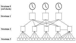
A stratum 2 server is connected to the stratum 1 server; then a stratum 3 server is connected to the stratum 2 server and so on. A stratum 2 server gets its time via NTP packet requests from a stratum 1 server. A stratum 3 server gets its time via NTP packet requests from a stratum-2 server… A stratum server may also peer with other stratum servers at the same level to provide more stable and robust time for all devices in the peer group (for example a stratum 2 server can peer with other stratum 2 servers).
Question 2
Explanation
The “ntp broadcast client” command is used under interface mode to allow the device to receive Network Time Protocol (NTP) broadcast packets on that interface
Reference: http://www.cisco.com/c/en/us/td/docs/ios/12_2/configfun/command/reference/ffun_r/frf012.html#wp1123148
Question 3
Question 4
Explanation
The stratum levels define the distance from the reference clock. A reference clock is a stratum 0 device that is assumed to be accurate and has little or no delay associated with it. Stratum 0 servers cannot be used on the network but they are directly connected to computers which then operate as stratum-1 servers. A stratum 1 time server acts as a primary network time standard.
A stratum 2 server is connected to the stratum 1 server; then a stratum 3 server is connected to the stratum 2 server and so on. A stratum 2 server gets its time via NTP packet requests from a stratum 1 server. A stratum 3 server gets its time via NTP packet requests from a stratum-2 server. Therefore the lower the stratum level is, the more accurate the NTP server is. When multiple NTP servers are configured, the client will prefer the NTP server with the lowest stratum level.
NTP uses User Datagram Protocol (UDP) port 123.
Question 5
Explanation
First we need to understand some basic knowledge about NTP. There are two types of NTP messages:
+ Control messages: for reading and writing internal NTP variables and obtain NTP status information. It is not used for time synchronization so we will not care about them in this question.
+ Request/Update messages: for time synchronization. Request messages ask for synchronization information while Update messages contains synchronization information and may change the local clock.
There are four types of NTP access-groups exist to control traffic to the NTP services:
+ Peer: controls which remote devices the local device may synchronize. In other words, it permits the local router to respond to NTP request and accept NTP updates.
+ Serve: controls which remote devices may synchronize with the local device. In other words, it permits the local router to reply to NTP requests, but drops NTP update. This access-group allows control messages.
+ Serve-only: controls which remote devices may synchronize with the local device. In other words, it permits the local router to respond to NTP requests only. This access-group denies control messages.
+ Query-only: only accepts control messages. No response to NTP requests are sent, and no local system time synchronization with remote system is permitted.
From my experience, you just need to remember:
+ Peer: serve and to be served
+ Serve: serve but not to be served |
Therefore in this question:
+ The “ntp access-group peer 2” command says “I can only accept NTP updates and respond to NTP (time) requests from 192.168.1.4“. -> Answer F is correct while answer D is not correct.
+ The “ntp access-group serve 1” command says “I can only reply to time requests (but cannot accept time update) from 192.168.1.1 ” -> Answer A is correct*
The “ntp master 4” indicates it is running as a time source with stratum level of 4 -> Answer B is not correct while answer C is correct.
Answer E is not correct because it can accept time requests from both 192.168.1.1 and 192.168.1.4.
*Note: In fact answer A is incorrect too because the local router can accept time requests from both 192.168.1.1 and 192.168.1.4 (not only from 192.168.1.1). Maybe this is an mistake of this question.
Question 6
Explanation
To control access to Network Time Protocol (NTP) services on the system, use the ntp access-group command in global configuration mode.
NTP supports “Control messages” and “Request/Update messages”.
+ Control messages are for reading and writing internal NTP variables and obtaining NTP status information. Not to deal with time synchronization itself.
+ NTP request/Update messages are used for actual time synchronization. Request packet obviously asks for synchronization information, and update packet contains synchronization information, and may change local clock.
When synchronizing system clocks on Cisco IOS devices only Request/Update messages are used. Therefore in this question we only care about “NTP Update message”.
Syntax:
ntp access-group [ipv4 | ipv6] {peer | query-only | serve | serve-only} {access-list-number | access-list-number-expanded | access-list-name} [kod]
+ Peer: permits router to respond to NTP requests and accept NTP updates. NTP control queries are also accepted. This is the only class which allows a router to be synchronized by other devices -> not correct. In other words, the peer keyword enables the device to receive time requests and NTP control queries and to synchronize itself to the servers specified in the access list.
+ Serve-only: Permits router to respond to NTP requests only. Rejects attempt to synchronize local system time, and does not access control queries. In other words, the serve-only keyword enables the device to receive only time requests from servers specified in the access list.
+ Serve: permits router to reply to NTP requests, but rejects NTP updates (e.g. replies from a server or update packets from a peer). Control queries are also permitted. In other words, the serve keyword enables the device to receive time requests and NTP control queries from the servers specified in the access list but not to synchronize itself to the specified servers -> this option is surely correct.
In summary, the answer “serve” is surely correct but the answer “serve-only” seems to be correct too (although the definition is not clear).
An example of using the “ntp access-group” command is shown below:
R1(config)#ntp server 178.240.12.1
R1(config)#access-list 2 permit 165.16.4.1 0.0.0.0
R1(config)#access-list 2 deny any
R1(config)#ntp access-group peer 2 // peer only to 165.16.4.1
R1(config)#access-list 3 permit 160.1.0.0 0.0.255.255
R1(config)#access-list 3 deny any
R1(config)#ntp access-group serve-only 3 //provide time services only to internal network 160.1.0.0/16 |
Reference:
+ http://www.cisco.com/c/en/us/td/docs/ios-xml/ios/bsm/command/bsm-cr-book/bsm-cr-n1.html
+ http://blog.ine.com/2008/07/28/ntp-access-control/
Question 7
Question 8
Explanation
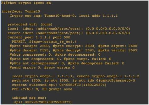
The output indicates that the local device did not receive the NTP update successfully so something went wrong during the transmission.
Question 9
Explanation
NTP operates in four different modes.
+ Server Mode is configured such that a device will synchronize NTP clients. Servers can be configured to synchronize all clients or only a specific group of clients. NTP servers, however, will not accept synchronization information from their clients. This restriction will not allow clients to update or manipulate a server’s time settings.
+ Client Mode is configured used to allow a device to set its clock by and synchronized by an external timeserver. NTP clients can be configured to use multiple servers to set their local time and can be configured to give preference to the most accurate time sources available to them. They will not, however, provide synchronization services to any other devices.
+ Peer Mode is when one NTP-enabled device does not have any authority over another. With the peering model, each device will share its time information with its peer. Additionally, each device can also provide time synchronization to the other.
+ Broadcast/Multicast Mode is a special server mode where the NTP server broadcasts its synchronization information to all clients. Broadcast mode requires that clients be on the same subnet as the server, and multicast mode requires that clients and servers have multicast capabilities configured.
Reference: http://www.pearsonitcertification.com/articles/article.aspx?p=1851440
“Interface” is not a NTP mode so answer A is not correct.
It is sure that in “peer” mode we don’t need to use the “trusted-key” command for authentication so answer C is not correct.
Question 10
Explanation
An example of the output of this command is shown below:
Router#show ntp associations
      address         ref clock     st  when  poll reach  delay  offset    disp
*~10.1.2.65        10.1.2.33        11    36    64  377    27.9   25.17    30.0
 * master (synced), # master (unsynced), + selected, - candidate, ~ configured
If there’s an asterisk (*) next to a configured peer, then you are synced to this peer and using them as the master clock. As long as one peer is the master then everything is fine. However, the key to knowing that NTP is working properly is looking at the value in the reach field.
The reach field is a circular bit buffer. It gives you the status of the last eight NTP messages (eight bits in octal is 377, so you want to see a reach field value of 377). If an NTP response packet is lost, the missing packet is tracked over the next eight NTP update intervals in the reach field. For more information about this field please read http://www.cisco.com/c/en/us/support/docs/ios-nx-os-software/ios-software-releases-110/15171-ntpassoc.html
Question 11
Question 12
Explanation
The command “ntp master [stratum]” is used to configure the device as an authoritative NTP server. You can specify a different stratum level from which NTP clients get their time synchronized. The range is from 1 to 15.
The stratum levels define the distance from the reference clock. A reference clock is a stratum 0 device that is assumed to be accurate and has little or no delay associated with it. Stratum 0 servers cannot be used on the network but they are directly connected to computers which then operate as stratum-1 servers. A stratum 1 time server acts as a primary network time standard.
A stratum 2 server is connected to the stratum 1 server; then a stratum 3 server is connected to the stratum 2 server and so on. A stratum 2 server gets its time via NTP packet requests from a stratum 1 server. A stratum 3 server gets its time via NTP packet requests from a stratum-2 server… A stratum server may also peer with other stratum servers at the same level to provide more stable and robust time for all devices in the peer group (for example a stratum 2 server can peer with other stratum 2 servers).

 Suppose you only want to allow the hosts inside your company to telnet to an outside server but not vice versa, you can simply use an “established” access-list like this: