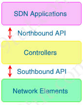
|
Quick Wireless Summary
Cisco Access Points (APs) can operate in one of two modes: autonomous or lightweight
+ Autonomous: self-sufficient and standalone. Used for small wireless networks. Each autonomous AP must be configured with a management IP address so that it can be remotely accessed using Telnet, SSH, or a web interface. Each AP must be individually managed and maintained unless you use a management platform such as Cisco DNA Center.
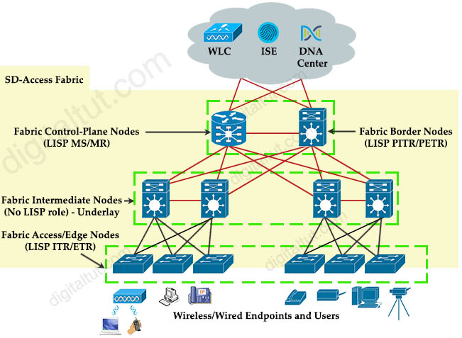
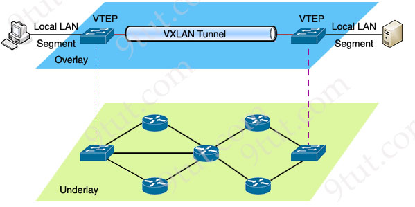
+ Lightweight: The term ‘lightweight’ refers to the fact that these devices cannot work independently. A Cisco lightweight AP (LAP) has to join a Wireless LAN Controller (WLC) to function. LAP and WLC communicate with each other via a logical pair of CAPWAP tunnels.
– Control and Provisioning for Wireless Access Point (CAPWAP) is an IETF standard for control messaging for setup, authentication and operations between APs and WLCs. CAPWAP is similar to LWAPP except the following differences:
+ CAPWAP uses Datagram Transport Layer Security (DTLS) for authentication and encryption to protect traffic between APs and controllers. LWAPP uses AES.
+ CAPWAP has a dynamic maximum transmission unit (MTU) discovery mechanism.
+ CAPWAP runs on UDP ports 5246 (control messages) and 5247 (data messages)
An LAP operates in one of six different modes:
+ Local mode (default mode): It offers one or more basic service sets (BBS) on a specific channel. AP maintains a tunnel towards its Wireless Controller. When the AP is not transmitting wireless client frames, it measures noise floor and interference, and scans for intrusion detection (IDS) events every 180 seconds.
+ FlexConnect, formerly known as Hybrid Remote Edge AP (H-REAP), mode: allows data traffic to be switched locally and not go back to the controller if the CAPWAP to the WLC is down. The FlexConnect AP can perform standalone client authentication and switch VLAN traffic locally even when it’s disconnected to the WLC (Local Switched). FlexConnect AP can also tunnel (via CAPWAP) both user wireless data and control traffic to a centralized WLC (Central Switched). The AP can locally switch traffic between a VLAN and SSID when the CAPWAP tunnel to the WLC is down.
+ Monitor mode: does not handle data traffic between clients and the infrastructure. It acts like a sensor for location-based services (LBS), rogue AP detection, and IDS
+ Rogue detector mode: monitor for rogue APs. It does not handle data at all.
+ Sniffer mode: run as a sniffer and captures and forwards all the packets on a particular channel to a remote machine where you can use protocol analysis tool (Wireshark, Airopeek, etc) to review the packets and diagnose issues. Strictly used for troubleshooting purposes.
+ Bridge mode: bridge together the WLAN and the wired infrastructure together.
+ Sensor mode: this is a special mode which is not listed in the books but you need to know. In this mode, the device can actually function much like a WLAN client would associating and identifying client connectivity issues within the network in real time without requiring an IT or technician to be on site.
Mobility Express is the ability to use an access point (AP) as a controller instead of a real WLAN controller. But this solution is only suitable for small to midsize, or multi-site branch locations where you might not want to invest in a dedicated WLC. A Mobility Express WLC can support up to 100 APs.
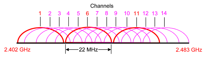
The 2.4 GHz band is subdivided into multiple channels each allotted 22 MHz bandwidth and separated from the next channel by 5 MHz.
-> A best practice for 802.11b/g/n WLANs requiring multiple APs is to use non-overlapping channels such as 1, 6, and 11.
Antenna
An antenna is a device to transmit and/or receive electromagnetic waves. Electromagnetic waves are often referred to as radio waves. Most antennas are resonant devices, which operate efficiently over a relatively narrow frequency band. An antenna must be tuned (matched) to the same frequency band as the radio system to which it is connected otherwise reception and/or transmission will be impaired.
Types of external antennas:
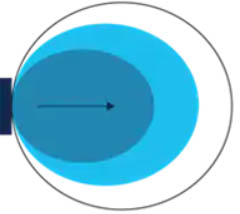
+ Omnidirectional: Provide 360-degree coverage. Ideal in houses and office areas. This type of antenna is used when coverage in all directions from the antenna is required.

Omnidirectional Antenna Radiation Pattern
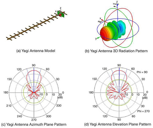
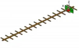
+ Directional: Focus the radio signal in a specific direction. Typically, these antennas have one main lobe and several minor lobes. Examples are the Yagi and parabolic dish
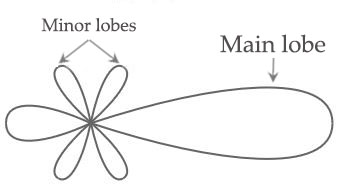 Yagi Antenna Radiation Pattern Yagi Antenna Radiation Pattern
+ Multiple Input Multiple Output (MIMO) – Uses multiple antennas (up to eight) to increase bandwidth
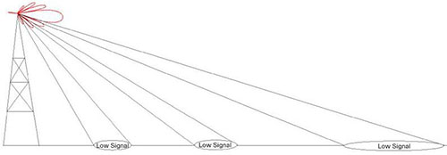
A real example of how the lobes affect the signal strength:
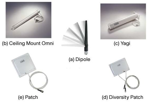
Common Antennas
Commonly used antennas in a WLAN system are dipoles, omnidirectional antennas, patches and Yagis as shown below:
Antenna Radiation Patterns
Dipole
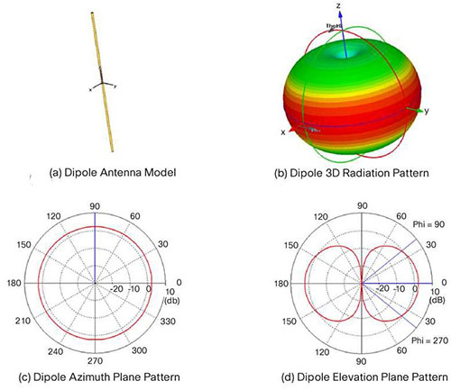
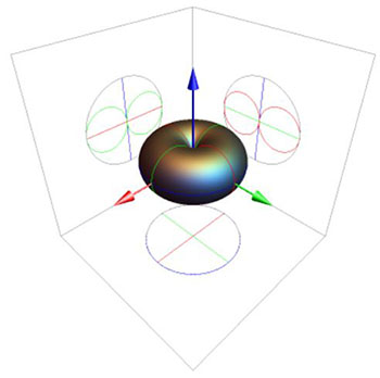
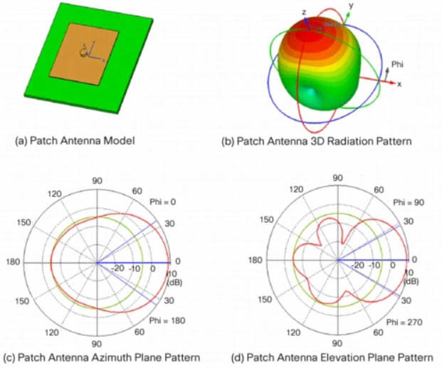
A more comprehensive explanation of how we get the 2D patterns in (c) and (d) above is shown below:
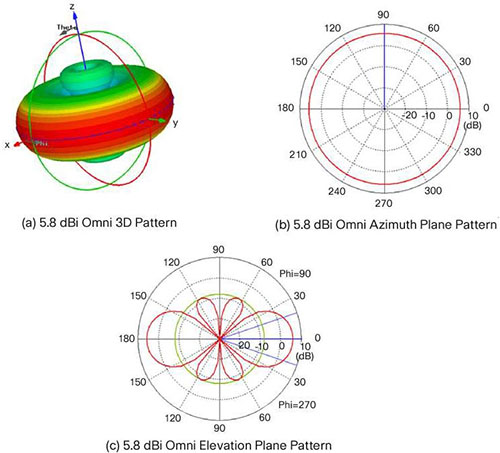
Omni
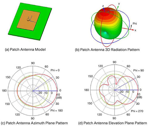
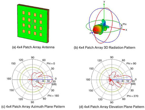
Patch
4 x 4 Patch
 Yagi Yagi
Wireless Terminologies
Decibels
Decibels (dB) are the accepted method of describing a gain or loss relationship in a communication system. If a level is stated in decibels, then it is comparing a current signal level to a previous level or preset standard level. The beauty of dB is they may be added and subtracted. A decibel relationship (for power) is calculated using the following formula:

“A” might be the power applied to the connector on an antenna, the input terminal of an amplifier or one end of a transmission line. “B” might be the power arriving at the opposite end of the transmission line, the amplifier output or the peak power in the main lobe of radiated energy from an antenna. If “A” is larger than “B”, the result will be a positive number or gain. If “A” is smaller than “B”, the result will be a negative number or loss.
You will notice that the “B” is capitalized in dB. This is because it refers to the last name of Alexander Graham Bell.
Note:
+ dBi is a measure of the increase in signal (gain) by your antenna compared to the hypothetical isotropic antenna (which uniformly distributes energy in all directions) -> It is a ratio. The greater the dBi value, the higher the gain and the more acute the angle of coverage.
+To divide one number by another, simply subtract their equivalent decibel values. For example, to find 100 divided by 10:
100÷10 = log100 – log10= 20dB – 10dB = 10dB = 10
+ dBm is a measure of signal power. It is the the power ratio in decibel (dB) of the measured power referenced to one milliwatt (mW). The “m” stands for “milliwatt”.
Example:
At 1700 MHz, 1/4 of the power applied to one end of a coax cable arrives at the other end. What is the cable loss in dB?
Solution:

=> Loss = 10 * (- 0.602) = – 6.02 dB
From the formula above we can calculate at 3 dB the power is reduced by half. Loss = 10 * log (1/2) = -3 dB; this is an important number to remember.
Beamwidth
The angle, in degrees, between the two half-power points (-3 dB) of an antenna beam, where more than 90% of the energy is radiated.

A radiation pattern defines the variation of the power radiated by an antenna as a function of the direction away from the antenna.
Polarization describes the way the electric field of the radio wave is oriented.
Antenna gain is the ability of the antenna to radiate more or less in any direction compared to a theoretical antenna.
OFDM
OFDM was proposed in the late 1960s, and in 1970, US patent was issued. OFDM encodes a single transmission into
multiple sub-carriers. All the slow subchannel are then multiplexed into one fast combined channel.
The trouble with traditional FDM is that the guard bands waste bandwidth and thus reduce capacity. OFDM selects channels that overlap but do not interfere with each other.

OFDM works because the frequencies of the subcarriers are selected so that at each subcarrier frequency, all other subcarriers do not contribute to overall waveform.
In this example, three subcarriers are overlapped but do not interfere with each other. Notice that only the peaks of each subcarrier carry data. At the peak of each of the subcarriers, the other two subcarriers have zero amplitude.

Basic Service Set (BSS)
A group of stations that share an access point are said to be part of one BSS.
Extended Service Set (ESS)
Some WLANs are large enough to require multiple access points. A group of access points connected to the same WLAN are known as an ESS. Within an ESS, a client can associate with any one of many access points that use the same Extended service set identifier (ESSID). That allows users to roam about an office without losing wireless connection.
Roaming
Roaming is the movement of a client from one AP to another while still transmitting. Roaming can be done across different mobility groups, but must remain inside the same mobility domain. The wireless client makes decisions on whether to change APs or remain connected to the current AP. There are 2 types of roaming:
A client roaming from AP1 to AP2. These two APs are in the same mobility group and mobility domain

Roaming in the same Mobility Group
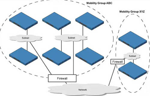
A client roaming from AP1 to AP2. These two APs are in different mobility groups but in the same mobility domain

Roaming in different Mobility Groups (but still in the same Mobility Domain)
Layer 2 & Layer 3 Intercontroller Roam
When a mobile client roams from one AP to another, and if those APs are on different WLCs, then the client makes an intercontroller roam.
When a client starts an intercontroller roam, the two WLCs compare the VLAN IDs allocated to their WLAN interfaces.
– If the VLAN IDs are the same, the client performs a Layer 2 intercontroller roam.
– If the VLAN IDs are different, the WLCs will arrange a Layer 3 or local-to-foreign roam.
Both of the roaming above allow the client to continue using its current IP address on the new AP and WLC.
In a Layer 3 roaming, the original WLC is called the anchor controller, and the WLC where the roamed client is reassociated is called the foreign controller. The client is anchored to the original WLC even if it roams to different controllers.
Wireless Parameters
Noise
There is radio frequency (RF) everywhere, from human activity, earth heat, space… The amount of unwanted RF is called noise.
Effective Isotropic Radiated Power (EIRP)
EIRP tells you what is the actual transmit power of the antenna. EIRP is a very important parameter because it is regulated by governmental agencies in most countries. In those cases, a system cannot radiate signals higher than a maximum allowable EIRP. To find the EIRP of a system, simply add the transmitter power level to the antenna gain and subtract the cable loss.
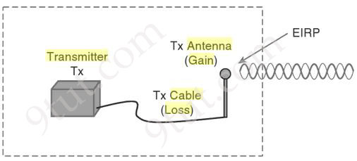
EIRP = Tx Power – Tx Cable + Tx Antenna
Suppose a transmitter is configured for a power level of 10 dBm. A cable with 5-dB loss connects the transmitter to an antenna with an 8-dBi gain. The resulting EIRP of the system is EIRP = 10 dBm – 5 dB + 8 dBi = 13 dBm.
You might notice that the EIRP is made up of decibel-milliwatt (dBm), dB relative to an isotropic antenna (dBi), and decibel (dB) values. Even though the units appear to be different, you can safely combine them because they are all in the dB “domain”.
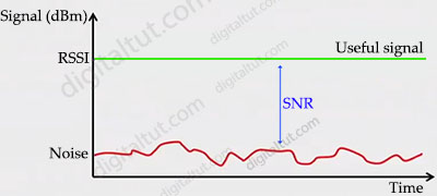
Receive Signal Strength Indicator (RSSI)
RSSI is a measurement of how well your device can hear a signal from an access point or router (useful signal). It’s a value that is useful for determining if you have enough signal to get a good wireless connection.
Signal-to-noise ratio (SNR or S/N)
SNR is the ratio of received signal power (at wireless client) to the noise power, and its unit of expression is typically decibels (dB). If your signal power and noise power are already in decibel form, then you can subtract the noise power from the signal power: SNR = S – N. This is because when you subtract logarithms, it is the equivalent of dividing normal numbers. Also, the difference in the numbers equals the SNR.For example, if the noise floor is -80 dBm and the wireless client is receiving a signal of -65 dBm SNR = -65 – (-80) = 15.
Or we can find SNR from RSSI with this formula: SNR = RSSI – N, with N is the noise power.
A practical example to calculate SNR
Here is an example to tie together this information to come up with a very simple RF plan calculator for a single AP and a single client.
+ Access Point Power = 20 dBm
+ 50 foot antenna cable = – 3.35 dB Loss
+ External Access Point Antenna = + 5.5 dBi gain
+ Signal attenuation due to glass wall with metal frame = -6 dB
+ RSSI at WLAN Client = -75 dBm at 100ft from the AP
+ Noise level detected by WLAN Client = -85 dBm at 100ft from the AP
Based on the above, we can calculate the following information:
+ EIRP of the AP at source = 20 – 3.35 + 5.5 = 22.15 dBm
+ Transmit power as signal passes through glass wall = 22.15 – 6 = 16.15 dBm
+ SNR at Client = -75 + -85 = 10 dBm (difference between Signal and Noise)
WPA2 and WPA3
WPA2 is classified into two versions to encrypt Wi-Fi networks:
+ WPA2-Personal uses pre-shared key (PSK)
+ WPA2-Enterprise uses advanced encryption standard (AES)
Similar to WPA2, WPA3 includes:
+ WPA3-Personal: applies to small-scale networks (individual and home networks).
+ WPA3-Enterprise: applies to medium- and large-sized networks with higher requirements on network management, access control, and security, and uses more advanced security protocols to protect sensitive data of users.
WPA3 provides improvements to the general Wi-Fi encryption, thanks to Simultaneous Authentication of Equals (SAE) replacing the Pre-Shared Key (PSK) authentication method used in prior WPA versions. SAE enables individuals or home users to set Wi-Fi passwords that are easier to remember and provide the same security protection even if the passwords are not complex enough.
WPA3 requires the use of Protected Management Frames. These frames help protect against forging and eavesdropping.
Wifi 6 (802.11ax)
Wifi 6 is an IEEE standard for wireless local-area networks (WLANs) and the successor of 802.11ac. Wi-Fi 6 brings several crucial wireless enhancements for IT administrators when compared to Wi-Fi 5. The first significant change is using 2.4 GHz. Wi-Fi 5 was limited to only using 5 GHz. While 5 GHz is a ‘cleaner’ band of RF, it doesn’t penetrate walls and 2.4 GHz and requires more battery life. For Wi-Fi driven IoT devices, 2.4 GHz will likely continue to be the band of choice for the foreseeable future.
Another critical difference between the two standards is the use of Orthogonal Frequency Division Multiple Access (OFDMA) and MU-MIMO. Wi-Fi 5 was limited to downlink only on MU-MIMO, where Wi-Fi 6 includes downlink and uplink. OFDMA, as referenced above, is also only available in Wi-Fi 6.
|

 When an EtherChannel is created, a logical interface will be created on the switches or routers representing for that EtherChannel. You can configure this logical interface in the way you want. For example, assign access/trunk mode on switches or assign IP address for the logical interface on routers…
 R1(config)#interface fa1/0
 Directional patch antenna
 Reference:
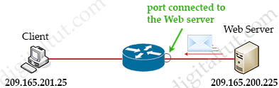
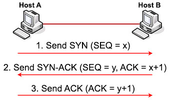
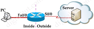 Suppose you only want to allow the hosts inside your company to telnet to an outside server but not vice versa, you can simply use an “established” access-list like this: